O p e rat i o n – MUTEC MC-4 User Manual
Page 16
\\\\\\\\\\\\
O P E RAT I O N
O P E RAT I O N
O P E RAT I O N
> > > > > > > > > > > > > > > > > > > > > > > > > > > > > > > > > > > > > > > > > > > > > > > > > > > > > > > > > > > > > > > > > > > >
> > > > > > > > > > > > > > > > > > > > > > > > > > > > > > > > > > > > > > > > > > > > > > > > > > > > > > > > > > > > > > > > > > > >
88
Manual SDs-01 E 3.2.2003 18:26 Uhr Seite 12
16
X-SRC
12
BI-DIR
UNI-DIR
ADAT
1
SMUX4
1
SRC
This setting e.g. allows for unidirectional format conversion (see »MODE«,
»UNI-DIR«) of an ADAT
TM
source signal with up to 50.0kHz sampling rate
(see »AUDIO
IN
«, »ADAT«) simultaneously to all available output formats.
The sampling rate of the source signal will be displayed in the first LED row,
marked with »1«, of the »CLOCK
IN
« menu. The ADAT
TM
signal will be re-clo-
cked and transfered to both optical ADAT
TM
outputs. Thus, the original input
signal is not lost and available for two times for further use!
Under »REFERENCE« the »ADAT« option is selected automatically. Please
see the passage below »Why a Clock Reference for unidirectional ADAT
TM
Conversion without SRC?« for more information on that.
Within the »AUDIO
IN
« menu, you can select with the »SELECT« button the
other available digital audio inputs. The reference for the selected audio
format will be activated accordingly.
Why a Clock Reference for unidirectional ADAT
TM
Conversion without SRC?
To allow for ADAT
TM
format conversion without SRC into AES3 and S/P-DIF,
the MC-4 needs to derive a valid clock signal from the incoming ADAT
TM
au-
dio source. Therefore, the corresponding reference option is activated in the
»REFERENCE« menu automatically. This selection can not be changed.
Converting 2-Channel Signals only
If an AES3 or S/P-DIF 2-channel stereo signal is input for format conversion
only (without SRC option), it is imperative to select under »REFERENCE« the
corresponding input number »IN1– IN4« as converting reference!
The sampling rate of the incoming AES3 or S/P-DIF signal will be displayed
in the »CLOCK
IN
« menu.
Converting multichannel AES3 or S/P-DIF Signals
When format converting multiple AES3 or S/P-DIF stereo signals to ADAT
TM
without using the SRC option, you must ensure that the individual stereo
input signals are all of equal and sychnronized sampling rates!
Further Setting Examples
REFERENCE
IN 3
IN 2
IN 1
IN 4
SMUX4
SMUX2
ADAT
AES3
88.2
48.0
44.1
32.0
192.0
96.0
176.4
MODE
SMUX2
1
AES3
2
AUDIO
IN
S/P-DIF
S/P-DIF
AES11
WCLK
Channel Assignment
The equal channel number assign-
ment of the multichannel audio
streams is guaranteed in all operations
modes of the MC-4.
!
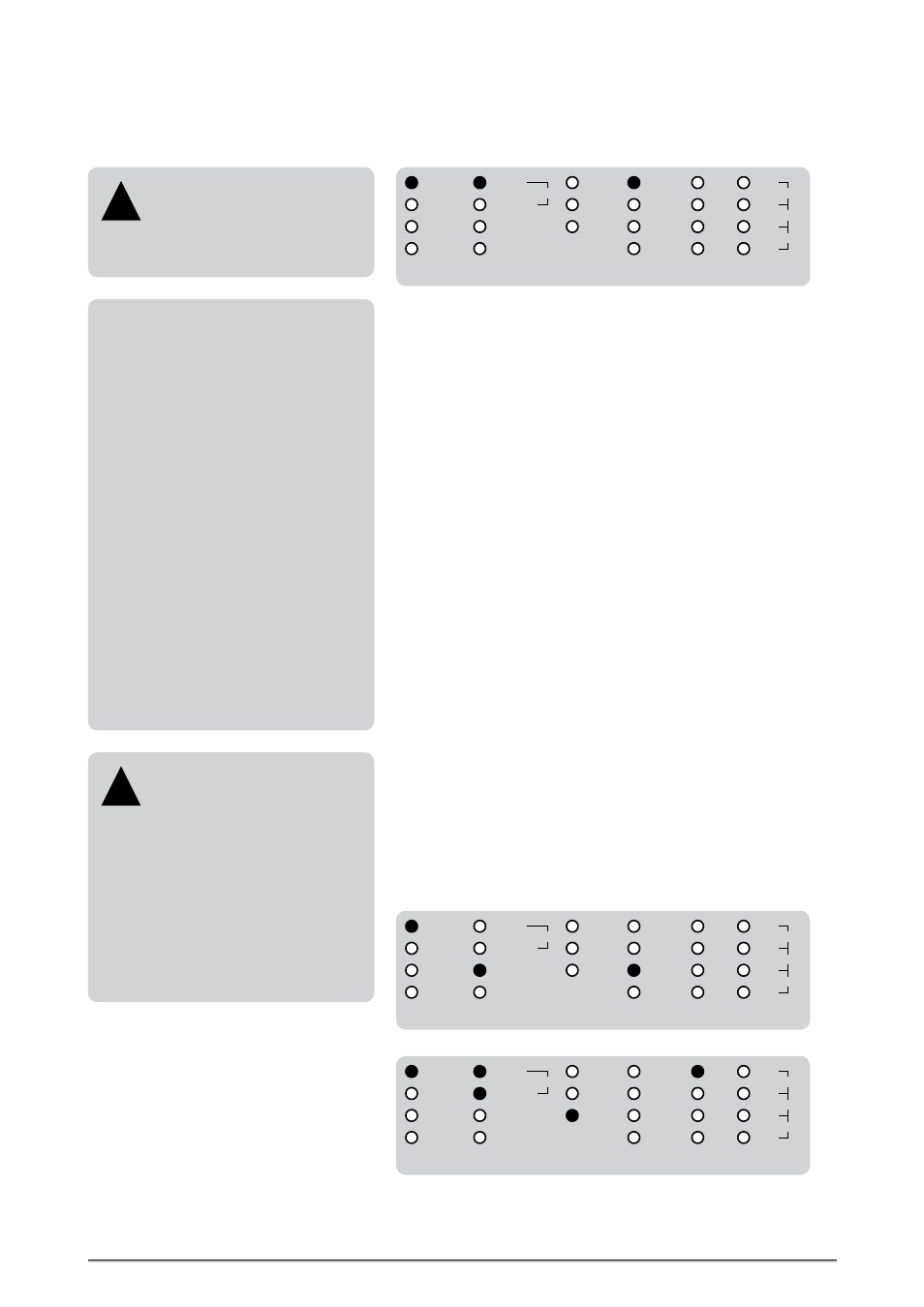
Unidirectional Format Conversions
X-SRC
12
BI-DIR
UNI-DIR
ADAT
1
SMUX4
1
SRC
REFERENCE
IN 3
IN 2
IN 1
IN 4
SMUX4
SMUX2
ADAT
AES3
88.2
48.0
44.1
32.0
192.0
96.0
176.4
MODE
SMUX2
1
AES3
2
AUDIO
IN
S/P-DIF
S/P-DIF
AES11
WCLK
Unidirectional format conversion from ADAT
TM
SMUX4 to AES3, S/P-DIF coaxial, ADAT
TM
SMUX4.
X-SRC
12
BI-DIR
UNI-DIR
ADAT
1
SMUX4
1
SRC
REFERENCE
IN 3
IN 2
IN 1
IN 4
SMUX4
SMUX2
ADAT
AES3
88.2
48.0
44.1
32.0
192.0
96.0
176.4
MODE
SMUX2
1
AES3
2
AUDIO
IN
S/P-DIF
S/P-DIF
AES11
WCLK
Unidirectional format conversion from S/P-DIF coaxial to AES3, ADAT
TM
. Here, a two channel
S/P-DIF signal only is applied at S/P-DIF input »1«, thus under »REFERENCE« the corresponding
clock reference »IN 1« is selected.
This is the only mode, in which the S/P-DIF interfaces work as inputs!
ADAT
TM
/ SMUX Adaption
When AES3 or S/P-DIF signals with
sampling rates up to 50.0kHz coming
in, both optical outputs transmit the same
ADAT
TM
signal and function as signal splitter.
Incoming AES3 or S/P-DIF signals with
50.0kHz to 100.0kHz sampling rates let the
optical output format switch to SMUX2.
Sampling rates of 100.0kHz to 200.0kHz of in-
coming AES3 or S/P-DIF signals let the optical
output format switch to SMUX4.
The corresponding SMUX format of the opti-
cal outputs is displayed under »STATUS«.
!
SMUX2 + SMUX4
The 8 channel ADAT
TM
format uses standard-
ly one optical connector and is limited to
sampling rates up to 50.0kHz. To enable the
use of higher sampling rates up to 192.0kHz,
SMUX2 or SMUX4 processing must be acti-
vated separately because these formats are
not decoded in the ADAT
TM
data stream for
automatic detection.
The SMUX2 process splits the ADAT
TM
stream
into two 4-channel blocks. Thus, both optical
inputs »A« and »B« must be used to input a
full 8-channel ADAT
TM
stream, whereas input
»A« receives channel 1– 4 and input »B« re-
ceives channel 5 – 8. SMUX2 transmits ADAT
streams with clock rates between 50.0kHz
and 100.0kHz.
SMUX4 works equally to SMUX2. Due to the
higher sampling rates, only 4 channels of an
8-channel ADAT
TM
stream can be processed.
Thus, the optical input »A« receives channel
1 + 2 and input »B« receives channel 3 + 4.
Channels 5 – 8 can no more processed with
SMUX4, which transmits ADAT
TM
streams with
sampling rates from 100.0kHz to 200.0kHz.