MUTEC MC-4 User Manual
Page 19
\\\\\\\\\\\\\\\\\\
A N H A N G
A N H A N G
A N H A N G
> > > > > > > > > > > > > > > > > > > > > > > > > > > > > > > > > > > > > > > > > > > > > > > > > > > > > > > > > > > > > > > > > > > >
> > > > > > > > > > > > > > > > > > > > > > > > > > > > > > > > > > > > > > > > > > > > > > > > > > > > > > > > > > > > > > > > > > > >
88
Manual SDs-01 D 3.2.2003 17:45 Uhr Seite 16
19
This setting allows e.g. to receive an ADAT
TM
signal with up to 50.0kHz
sampling rate and an 8-channel AES3 signal between 25.0kHz and 200.0kHz
simultaneously. The optical ADAT
TM
input signal is converted to AES3 and
the AES3 signals are converted to ADAT
TM
or SMUX2/4, depending on the
clock rate of the reference clock signal. The four AES3 stereo input and the
ADAT
TM
signals can consist of different sampling rates!
The sampling rate of all outputs now depends on the clock rate of the
applied reference clock signal, which is selected in the
»REFERENCE« menu. The example above shows the Word Clock selected as
clock reference (default setting).
In this mode, the following clock references are available for synchronizati-
on of the internal SRCs:
WCLK, SCLK
AES11 (through separate input at the rear)
ADAT
TM
, SMUX2, SMUX4
AES3 IN1– 4, every of the AES3 stereo inputs
Internal clock oscillator
To activate a clock source enter the »REFERENCE« menu and press the
»SELECT« button repeatedly. When the external clock reference signal can
be locked by the internal PLL circuit, the blue LED »LOCK
1
« in the STATUS
menu will light constantly. The clock rate of the selected clock source is
displayed in the »REF CLOCK
IN
« menu under »1«.
Individual AES3 Input Signals
Running the MC-4 in the SRC mode, the clock rates of indivudual AES3
input signals can be totally different within a range of 25.0kHz to 200.0kHz.
It is also not necessary to feed in signals at all four AES3 inputs. The input
assignment is passed to the outputs.
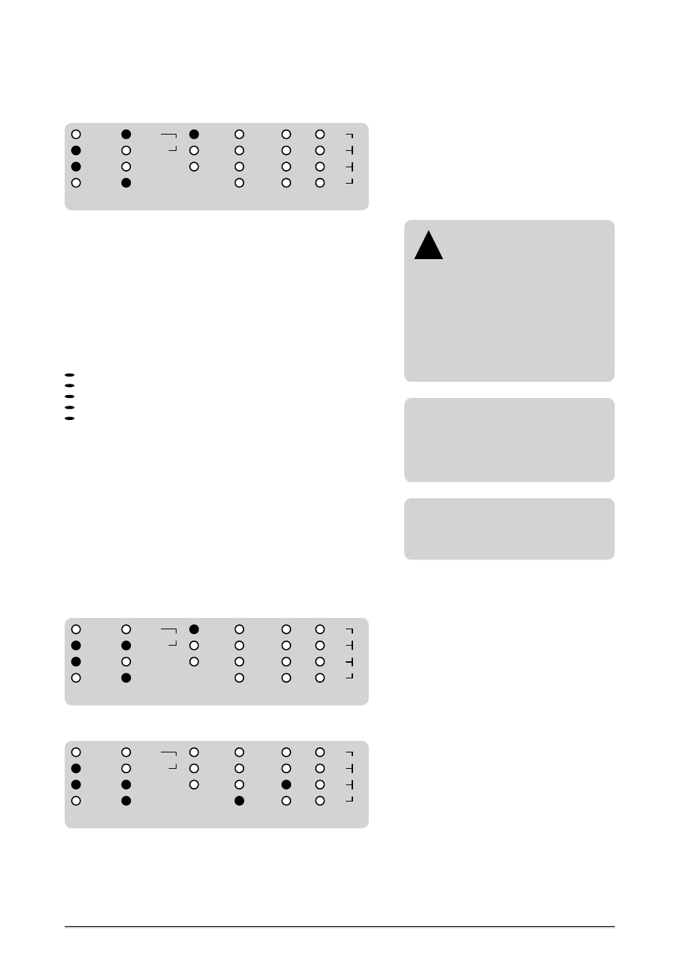
Further Setting Examples
In this conversion mode, the MC-4 accepts
the incoming AES3 signals with different
sampling rates per stereo input. Due to
this, it may be also useful to select one of
the stereo inputs as reference clock for the
internal SRCs!
X-SRC
12
BI-DIR
UNI-DIR
ADAT
1
SMUX4
1
SRC
REFERENCE
IN 3
IN 2
IN 1
IN 4
SMUX4
SMUX2
ADAT
AES3
88.2
48.0
44.1
32.0
192.0
96.0
176.4
MODE
SMUX2
1
AES3
2
AUDIO
IN
S/P-DIF
S/P-DIF
AES11
WCLK
Bidirectional Format and Sampling Rate Conversions
ADAT
TM
/ SMUX Adaption
with SRC Option
Does the reference clock signal not
exceed 50.0kHz, both optical outputs trans-
mit the same ADAT
TM
signal and the MC-4
functions as ADAT
TM
signal splitter.
If the reference clock exceeds 50.0kHz, the
optical output format will automatically
change to »SMUX2« or »SMUX4«, depending
on the reference signal‘s clock rate. The
corresponding SMUX format of the optical
outputs is displayed in the »STATUS« menu.
!
The S/P-DIF interfaces do not have any func-
tion in these bidirectional conversion modes,
due to the lack of simultaneous useable
inputs and outputs!
Bidirectional format and sampling rate conversion between SMUX2 and an 8-channel AES3 signal
referenced to a Word Clock signal. The sampling rate of the reference clock signal and the format of
the optical SMUX2 outputs are displayed in the »CLOCK IN« and »STATUS« menus.
X-SRC
12
BI-DIR
UNI-DIR
ADAT
1
SMUX4
1
SRC
REFERENCE
IN 3
IN 2
IN 1
IN 4
SMUX4
SMUX2
ADAT
AES3
88.2
48.0
44.1
32.0
192.0
96.0
176.4
MODE
SMUX2
1
AES3
2
AUDIO
IN
S/P-DIF
S/P-DIF
AES11
WCLK
Bidirectional format and sampling rate conversion between SMUX4 and an 8-channel AES3 signal
referenced to the third AES3 input signal. The sampling rate of the reference clock signal and the
format of the optical SMUX4 outputs are displayed in the »CLOCK IN« and »STATUS« menus.
X-SRC
12
BI-DIR
UNI-DIR
ADAT
1
SMUX4
1
SRC
REFERENCE
IN 3
IN 2
IN 1
IN 4
SMUX4
SMUX2
ADAT
AES3
88.2
48.0
44.1
32.0
192.0
96.0
176.4
MODE
SMUX2
1
AES3
2
AUDIO
IN
S/P-DIF
S/P-DIF
AES11
WCLK