MUTEC MC-4 User Manual
Page 18
\\\\\\\\\\\\\\\\\\
A N H A N G
A N H A N G
A N H A N G
> > > > > > > > > > > > > > > > > > > > > > > > > > > > > > > > > > > > > > > > > > > > > > > > > > > > > > > > > > > > > > > > > > > >
> > > > > > > > > > > > > > > > > > > > > > > > > > > > > > > > > > > > > > > > > > > > > > > > > > > > > > > > > > > > > > > > > > > >
88
Manual SDs-01 D 3.2.2003 17:45 Uhr Seite 16
18
This setting is a special function of your MC-4! It allows to receive an
ADAT
TM
signal with up to 50.0kHz sampling rate and an 8-channel AES3
signal between 25.0kHz and 200.0kHz simultaneously. The ADAT
TM
input
signal is converted to AES3 and the AES3 input signals are converted to
ADAT
TM
or SMUX2/4, depending on the common clock rate of the incoming
AES3 signals. The format of the optical outputs is changed automatically
and displayed in the »STATUS« menu.
In this mode, the MC-4 is able to work simultaneously with two different
sampling rates, each within the above mentioned frequency ranges. There-
fore, the system uses two PLL synthesizers to lock the incoming ADAT
TM
and AES3 signals with their individual clock rates. The status of the PLLs is
displayed in the »STATUS« and »CLOCK
IN
« menus. To distinguish between
the two PLL states, the two blue »LOCK« LEDs and the two raws of red
»CLOCK
IN
« LEDs are marked with small numbers »1« and »2«. The number
»1« indicates the state of the first PLL, which is standardly connected to the
incoming ADAT
TM
audio signal. Number »2« indicates the state of the se-
cond PLL connected to the incoming AES3 signals. To make this more clear,
we have also marked the two involved audio formats with small numbers:
»ADAT
1
« and »AES3
2
«.
Necessary Reference Assignment
To allow for bidirectional conversions between ADAT
TM
or SMUX2/4 and
AES3, the MC-4 needs to derive valid clock signals from the incoming audio
sources. Therefore, it is a must to activate one of the AES3 inputs »IN1 – 4«
in the »REFERENCE« menu, the default setting is »IN1«. The reference
»ADAT« or »SMUX2/4« is standardly activated due to the clock rate of the
incoming ADAT
TM
or SMUX signal and can not be changed in this mode.
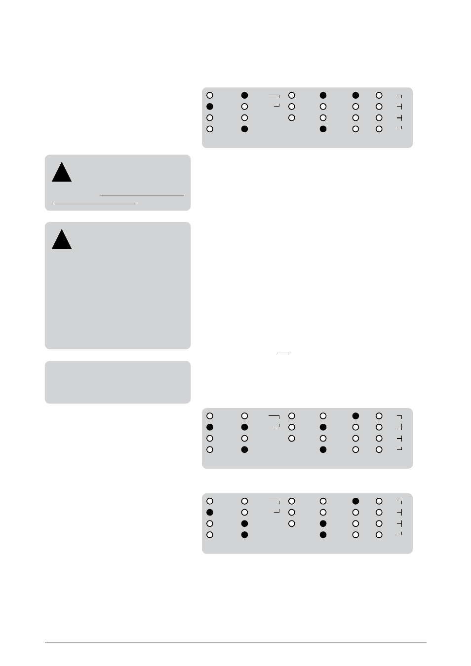
Further Setting Examples
Bidirectional format conversion between SMUX2 with clock rates from 50.0kHz to 100.0kHz and
an 8-channel AES3 signal. The sampling rates of the incoming audio signals and the format of the
optical SMUX2 outputs are displayed in the »STATUS« and »CLOCK IN« menus.
Equal Clock Rates for AES3!
Due to the fact, that this is a
format conversion mode only, it is
imperative that all AES3 signals are of same
synchronized sampling rates!
!
The S/P-DIF interfaces do not have any func-
tion in these bidirectional conversion modes,
due to the lack of simultaneous useable
inputs and outputs!
X-SRC
12
BI-DIR
UNI-DIR
ADAT
1
SMUX4
1
SRC
REFERENCE
IN 3
IN 2
IN 1
IN 4
SMUX4
SMUX2
ADAT
AES3
88.2
48.0
44.1
32.0
192.0
96.0
176.4
MODE
SMUX2
1
AES3
2
AUDIO
IN
S/P-DIF
S/P-DIF
AES11
WCLK
X-SRC
12
BI-DIR
UNI-DIR
ADAT
1
SMUX4
1
SRC
REFERENCE
IN 3
IN 2
IN 1
IN 4
SMUX4
SMUX2
ADAT
AES3
88.2
48.0
44.1
32.0
192.0
96.0
176.4
MODE
SMUX2
1
AES3
2
AUDIO
IN
S/P-DIF
S/P-DIF
AES11
WCLK
Bidirectional Format Conversions
ADAT
TM
/ SMUX Adaption
When AES3 signals with sampling
rates up to 50.0kHz coming in, both
optical outputs transmit the same ADAT
TM
signal and function as signal splitter.
Incoming AES3 signals with 50.0kHz to
100.0kHz sampling rates let the optical out-
put format switch to SMUX2.
Sampling rates of 100.0kHz to 200.0kHz of
incoming AES3 signals let the optical output
format change to SMUX4.
The corresponding SMUX format of the opti-
cal outputs is displayed under »STATUS«.
!
Bidirectional format conversion between SMUX4 with clock rates from 100.0kHz to 200.0kHz and
an 8-channel AES3 signal. The sampling rates of the incoming audio signals and the format of the
optical SMUX4 outputs are displayed in the »STATUS« and »CLOCK IN« menus.
X-SRC
12
BI-DIR
UNI-DIR
ADAT
1
SMUX4
1
SRC
REFERENCE
IN 3
IN 2
IN 1
IN 4
SMUX4
SMUX2
ADAT
AES3
88.2
48.0
44.1
32.0
192.0
96.0
176.4
MODE
SMUX2
1
AES3
2
AUDIO
IN
S/P- DIF
S/P-DIF
AES11
WCLK