Installation and operating instructions vpt series, Moniteur devices inc – Moniteur Indicateur VPT User Manual
Page 4
Moniteur Devices Inc
WIRING OF VALVE POSITION TRANSMITTER
1. Remove VPT cover from the housing by loosening
the screws. Holding the housing and cover
assembly together, lift the cover from the housing.
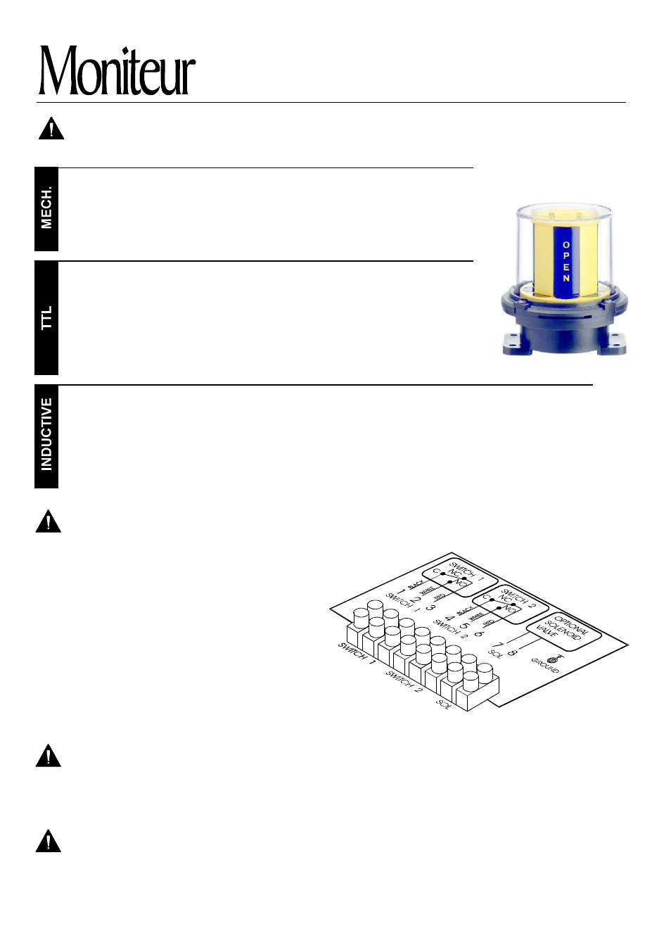
2. Follow the wiring diagram located inside the cover
of the VPT. Be sure to secure all the appropriate
connections including the ground. The diagram at
left relates the wiring diagram to the terminal block.
3. Replace the VPT cover and tighten the screws. To
ensure that the shaft alignment mechanism
functions properly, bring all of the screws in contact
with the cover and then tighten them in stages
moving from one screw to its diagonal counterpart.
ELECTRICAL SPECIFICATIONS
Switch Type
Cherry - SPDT
Prism Gold Plated - SPDT
ITW - DPDT
AC Rating
15A - 250V
1A - 120V
10A - 250V
Form
C
C
CC
DC Rating
2.5A - 24V
1A - 24V
7A - 24V
Code
1
3
4
Switch Type
Tungsten TTL - SPDT
Tungsten TTL HV - SPDT
Rhodium TTL - SPDT
Bifurcated TTL - SPST
Rhodium TTL - SPST
Krystal TTL - SPDT
AC Rating
3A - 120V
1A - 120V
3A - 120V
0.4A - 240V
1A - 120V
0.3A - 120V
DC Rating
2A - 24V
1A - 24V
2A - 24V
0.4A - 240 V
1A - 24V
0.3A - 24V
Form
C
C
A
C
C
A
Code
2
E
7
T
L
B
Sensor
P & F NBB3-V3-Z4
Moniteur NAMUR
Moniteur NEO-X
P & F NJ2-V3
Supply
Voltage
5-25 VDC
10-250 VAC/VDC
5-25 VDC
5-60 VDC
Operation
PNP
NAMUR
NO
NAMUR
Load Current /
Target Absent
< 1 mA
< 0.7 mA
< 1 mA
< 1 mA
Load Current /
Target Present
4 - 100 mA
3 - 15 mA
3 - 15 mA
3 - 300 mA
Code
8
K
M
A
Installation and Operating Instructions
VPT Series
1
2
3
4
5
6
7
8
WARNING (FOR ENCLOSURE TYPES 4, 4x, 7 and 9 ONLY): To prevent fire or explosion, use only with
a seal fitting within 18 inches of the position transmitter enclosure.
CAUTION: Always check that the electrical load is within the range stated on the nameplate. Failure to
adhere to the ratings may result in damage to or premature failure of the electrical switches or sensors.
TERMINAL BLOCK AND WIRING DIAGRAM
M O N I T E U R
D E V I C E S
I N C O R P O R A T E D
36 C omme rce R oad, Ceda r G rove , N J 0 700 9 Te l. (9 73) 8 5 7-16 00 Fa x (9 73) 8 5 7-7 289
w w w . m o n i t e u r d e v i c e s . c o m
Page 4
WARNING: All Inductive Sensors must be connected with the appropriate PLC, microprocessor or
relay load. Otherwise, damage can result to the sensors. Check the sensor installation sheet in the box.
CLEANING VALVE POSITION TRANSMITTER
If desired, use a damp rag or cloth to clean the outside of the position transmitter. No routine cleaning or
maintenance is required for reliable, long term operation of the device.
WARNING: If the equipment is used in a manner not specified by the manufacturer, the protection
provided by the equipment may be impaired.
Note: In Survivor II enclosures, Voltage and Current Ratings are lower, see Nameplate for appropriate ratings.