Moniteur Indicateur VPT User Manual
M y b 5 1 2 0, Moniteur devices inc
Moniteur Devices Inc
Installation and Operating Instructions
VPT Series - Form IO1-0202
DESCRIPTION OF DEVICE
Sentinel
The Moniteur Visual Indicator is a mechanical device that
graphically displays the angular displacement of a quarter
turn valve or any other device operating between 0 and 90
degrees. The Moniteur Indicator represents a true
indication of valve position. It is infinitely adjustable, and
delivers a 100% change of indication, displaying 90
degrees of rotation by utilizing an amplified mechanical
drive. Moniteur Valve Position Transmitters have
enclosures meeting the following requirements:
- Nema 4, 4x - Watertight, Nema 7
Explosion-proof and Nema 9 Dust - Ignition-proof,
Class 1, Division 1 Groups C&D, Class I, Division 1
Groups E, F, & G, Class 1, Division 2 Groups A, B
(TTL switches and Inductive Sensors only)
Nema 4, 4x Watertight, Nema 7
Explosion-proof and Nema 9 Dust - Ignition-proof,
Class 1, Division 1 Groups A, B, C&D, Class II,
Division 1, Groups E, F, & G
- Nema 4,
4x -Watertight
- Nema 4, 4x - Watertight,
Series ‘
Q’
(FM) Install per drawing no. S2CF
Non-incendive Division 2 All Groups
Series ‘
R’
(CSA)
Division 2 All Groups
The Survivor II unit must be supplied by an SELV
source in accordance with C22.2 No. 1010.1 Annex H.
Sentinel II -
Watchman / Watchman II / Survivor / Scout
Survivor II
M O N I T E U R
D E V I C E S
I N C O R P O R A T E D
36 C o mme rce Ro ad, Cedar G rove , NJ 0 700 9 Tel. (9 73) 8 57 -16 00 Fax (9 73) 8 57- 7 289
LONG
STD
NAMUR
NAMUR
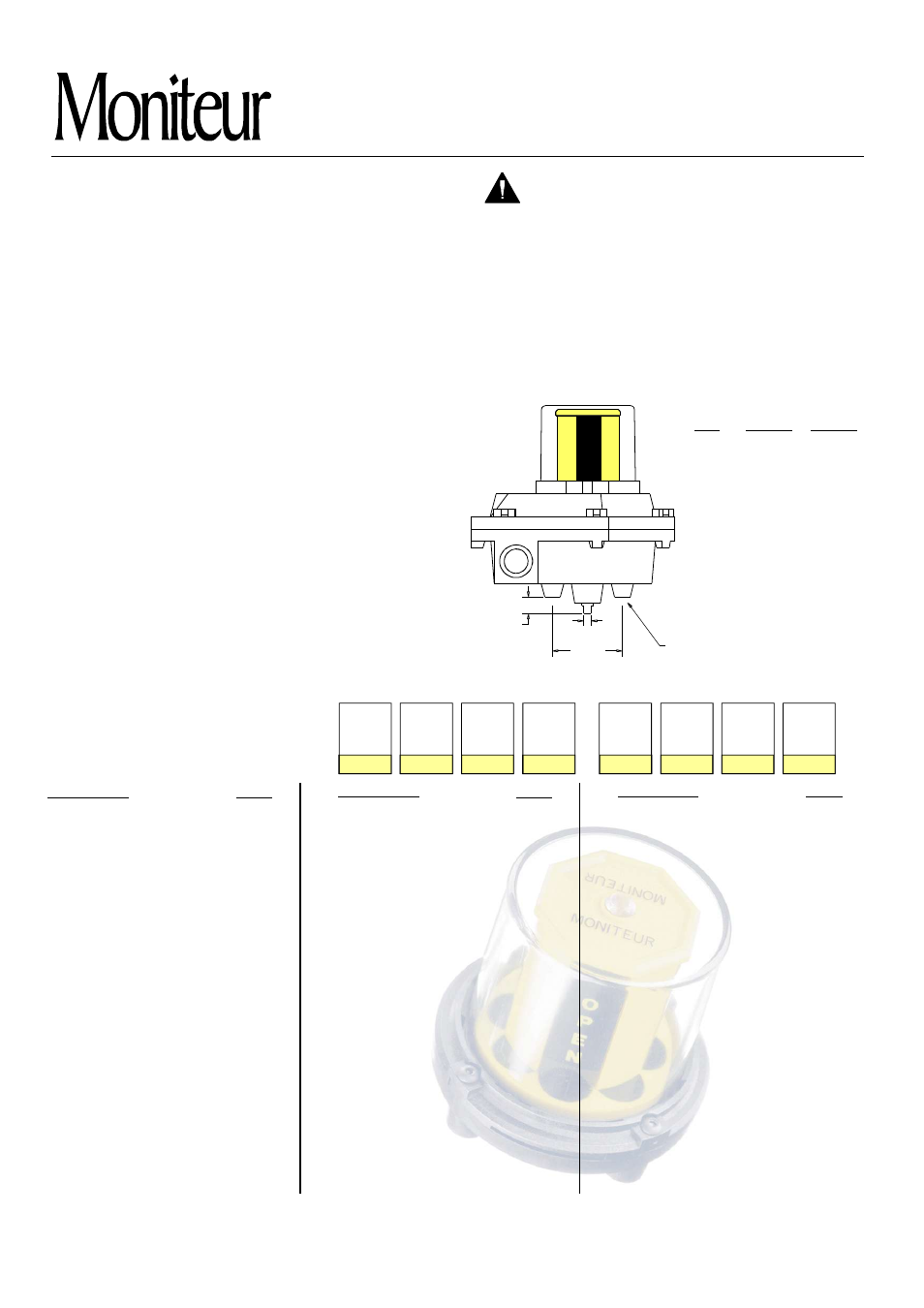
A
B
0.249
0.156
0.156
0.53
0.62
1.25
Moniteur Valve Position Transmitters can
be mounted in any position.
CAUTION: To reduce the risk of ignition of
hazardous atmospheres, disconnect the
device from the supply circuit before
opening. Keep assembly tightly closed
during operation.
Pollution Degree - "4"
Installation Category - "I”
Operating Temperature (deg. C) -40 to 80
Positioning-
Mounting Dimensions (for all switches)
A
-
Series
Cover
Moniteur
Bearing
Shaft
Switch
Quantity
Conduit
Description
Switch Type
Cherry 15A
SPDT Mechanical
Prism Gold Plated 1A
SPDT Mechanical
ITW 10A
DPDT Mechanical
Rhodium TTL 1A
SPST Non-Contact
Krystal TTL 0.3A
SPDT Non-Contact
NEO-X 0.3A
NO Sensor
Bearing
Shaft
Bronze
303 Stainless Steel
Standard 303 SS
Standard 316 SS
NAMUR
303 SS
Long NAMUR 303 SS
Tungsten TTL 3A
SPDT Non-Contact
Code
A
C
F
H
P
Q
R
V
I
M
F
N
Y
O,T,F
S
1
G,R,B
A
C
P
Code
B
S
1
3
5
E
1
2
3
4
7
L
A
Description
Series
Cover
Moniteur
Sentinel
Sentinel-II
Survivor
Survivor-II (FM)
Survivor-II (CSA)
Scout
With Moniteur
Flat Cover (No Moniteur)
Black / Yellow
Green, Red, Blue / White
Watchman
Watchman-II
Indicateur
No Indicator
3-Way Path O,T,F
4-Way Path S
180 degree “
T”
Green / Red
Red / Green
0-100%
Description
Switch Quantity
Conduit (Sentinel)
Output
Rhodium TTL 1A
SPDT Non-Contact
Bifurcated TTL 3A
SPST Non-Contact
P&F NJ2-V3 NAMUR
Inductive Sensor
P&F NBB3-V3-Z4
Inductive Sensor
(2) ¾" F NPT
(3) ¾ F
(2) ¾" F + (1) ½" F NPT
(add suffix to part number)
Current 4 - 20mA
Resistive 0 - 1k
(1) ¾ F + (1) ½ M NPT
Ω
Conduit (Watchman / Survivor)
(2) ½" F NPT
(3) ½" F NPT
(1) ½" F + (1) ½" M NPT
"
"
"
Code
T
B
8
K
1-6
0
6
8
0
5
6
8
- 420
- 1K
PART NUMBER SYSTEM
The series and part number are located
on the nameplate. The part number can
be deciphered in the table below.
M Y
B
5
1
2
0
B
A
SQ. BOLT PATTERN
5/16-18 (4x)
2.25
N
E
P
O
Form IO1-0202
w w w . m o n i t e u r d e v i c e s . c o m
Page 1