Installation and operating instructions vpt series, Moniteur devices inc, Fig. 1 – Moniteur Indicateur VPT User Manual
Page 2
Moniteur Devices Inc
INSTALLATION - ADJUSTING THE VISUAL INDICATOR
90 - 90
45 - 45
135 - 135
1. Mount the valve position transmitter to the valve or actuator with the
correct mounting bracket.
2. Determine the true valve position and compare the Moniteur's
Indication with the true valve position. If the Moniteur display is
synchronized, proceed to Step 12. If it is not, continue to Step 3.
3.
Determine the level of
adjustment that needs to be made. If only a small adjustment is
necessary (less than 20 degrees in either direction), proceed to step 4.
If a larger adjustment is required, such as 45, 90 or 135 degrees from
default, proceed to step 7.
4.
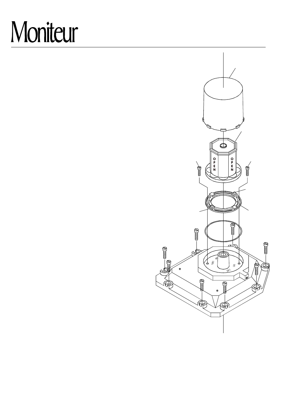
Loosen screws B and C shown in fig.1
(do not remove screws). The Infinite adjusting ring should rotate freely
over the enclosure cover of the Valve Position Transmitter.
5. Return the Moniteur Indicator to the output shaft. As it slides down
along the shaft, be sure that the Moniteur Indicator's base engages
the Infinite Adjusting Ring on pins “
E”
. (fig.1)
6. Rotate the Moniteur Indicator by applying a light rotational force to the
vertical vanes to synchronize it with the true valve position. Once
aligned, proceed to Step 9. If further adjustment is necessary, you will
need to continue with Step 7.
7.
Rotate the setting ring and match the number on
the plastic ring with the number cast into the enclosure, according to
the following requirements:
: as shipped from the factory - shipped as “
Open”
.
: “
Open”
is 45 degrees CCW in travel from default.
: Open”
is 45 degrees CW in travel from default.
Remove the clear Moniteur cover by turning it counter-clockwise to
disengage the detent and then lift it off.
Remove the Moniteur Visual Indicator by lifting it upward off the shaft
and the Infinite Adjusting Ring.
Remove the Moniteur Visual Indicator by lifting it upward off the shaft
and the Infinite Adjusting Ring. Remove screws B and C from the
Infinite Adjusting Ring.
“
: “
Open”
is 90 degrees CW or CCW from default.
(This is the setting to switch default indication from
Open to Closed.)
Now return the Moniteur
Indicator to the output shaft. Be sure that the Indicator's
base engages the infinite adjusting ring on pins “
E”
. (fig.1)
8. Rotate the Moniteur Indicator by applying a light rotational
force to the vertical vanes to further synchronize the
Indicator with the true valve position.
9. Remove the Moniteur Indicator, being careful not to rotate
the Infinite Adjustment Ring.
180 - 180
Return screws B and C to their appropriate threaded holes,
but do not tighten them completely.
Hold Ring stationary and
tighten screws B and C.
10. Return the Moniteur Indicator being certain that both the output shaft and pins “
E”
of the Infinite Adjusting Ring are engaged.
11. Return the clear Moniteur cover by inserting it into the breach lock on the
enclosure cover and turning it Clock-wise until the unit engages the detent.
12. Cycle the valve to the opposite extremity. If the Moniteur Indicator is displaying the
correct valve position, installation is complete. If not, it is probably because the
actuator is not moving exactly 90 degrees. Adjust the stroke of the actuator so that
it is rotating 90 degrees and the Moniteur Indicator will indicate the correct valve
position. Installation is now complete.
Fig. 1
M O N I T E U R
D E V I C E S
I N C O R P O R A T E D
36 C omme rce R oad, Ceda r G rove , N J 0 700 9 Te l. (9 73) 8 5 7-16 00 Fa x (9 73) 8 5 7-7 289
w w w . m o n i t e u r d e v i c e s . c o m
Page 2
M
O
N
IT
E
U
R
MONITEUR
45
1
8
0
Clear Cover
Moniteur
Screw “
C”
Screw “
B”
Pin “
E”
Pin “
E”
Adjusting
Ring “
A”
Installation and Operating Instructions
VPT Series