Identifying the parts 12 – MF Digital Teaс P55 SureThing Setup Guide User Manual
Page 5
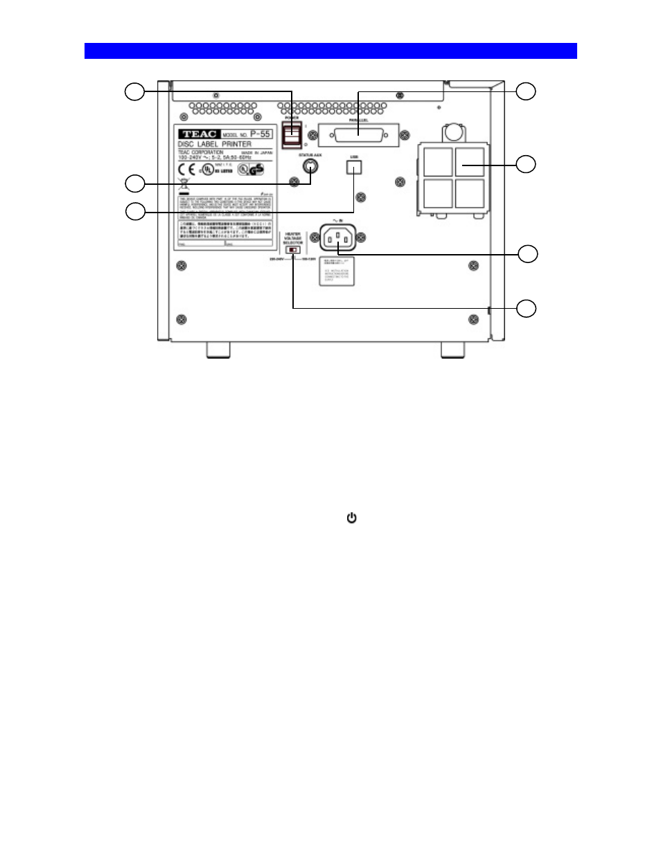
Identifying the Parts
12
STATUS AUX Connector (optional)
This connector allows connection of the P-55 to an extern al device for the combined use with the robotics system.
*Please contact us before use.
13
Parallel Port Multi-connector
This provides a parallel interface between your PC's printer port and the P-55 over the supplied
printer cable.
14
Intake Fan (with filter)
This opening is for dropping the temperature inside the unit. Obstructing this opening may
result in failures. Place the unit in an adequate location.
15
Power Switch
This rocker switch turns power to the unit on and off.
end of the switch, and powers down when pressing “
” end.
(The internal cooling fan stops only in about 10-20 minutes after the unit switches into the Standby ode.)
16
AC Power Input Socket
Plug in here the power cable. (To drop the tem perature inside the unit, the fan continues
to rotate for about 10 to 20 minutes after switching off the power. For this interval of time,
do not unplug the power cable.)
Connections .
17
Heater Voltage Selector Switch
This selects the voltage to supply to the internal heater.
For U.S.A. and Canada
The Heater Voltage Selector Switch is preset to “100-120V” at the factory.
Selecting a wrong voltage may cause the printer to malfunction.
For Europe
The Heater Voltage Selector Switch is preset to “220-240V” at the factory.
Selecting a wrong voltage may cause the printer to malfunction.
18
USB 2.0 Compatible Connector (Hi-Speed support)
12
18
15
13
14
17
16