Make Noise Wogglebug User Manual
Page 6
19
14
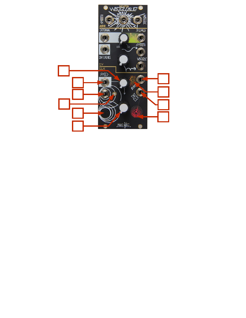
Panel Controls: (cont’d)
CLK:
12. Speed CV Attenuator: unipolar attenuator for Speed CV IN. Normalled to 8V (see below).
13. Speed CV IN: unipolar control signal input for Speed parameter. Normalled to +8V so that with
nothing patched, the associated Speed CV attenuator will extend the internal clock generator
range up to around 200hz; Range: 0V to +8V.
14. External Clock IN: any signal may be applied here, allowing for independent control of
rate and smoothness.
15. System Clock LED: Displays rate of Sample and Hold clock. When a signal is applied to the
External Clock In, shows the rate of the incoming clock/rising edge. With nothing patched, will
mirror the Internal clock.
16. Disturb Button: Direct control of the Sample and Hold circuit: pressing Samples; holding Holds.
17. Speed Control: dual purpose control that sets the Rate of the Wogglebug Internal Clock
generator & the lag processor feeding the Smooth CV circuit. Turning it CCW slows the system
and smoothes its response. Turning it CW quickens the system with the Smooth CV response
becoming jittery. Internal Clock generator range is 1 minute per cycle up to around 40hz
(extended range pushes upper limit to around 200hz).
18. Burst OUT: Square random gate signal, synced to the Clock and influenced by the Stepped,
Smooth and Woggle controls; 0 to +10V.
19. Burst OUT LED: Visual respresentation of random gates.
20. Clock OUT: Square clock signal from the internal clock generator. Not influenced by signal at
External Clock IN; 0V to +10V.
21. Internal clock LED: Displays rate of internal clock. NOT affected by External Clock In.
13
16
15
18
20
12
17
21