Make Noise Rosie User Manual
Page 4
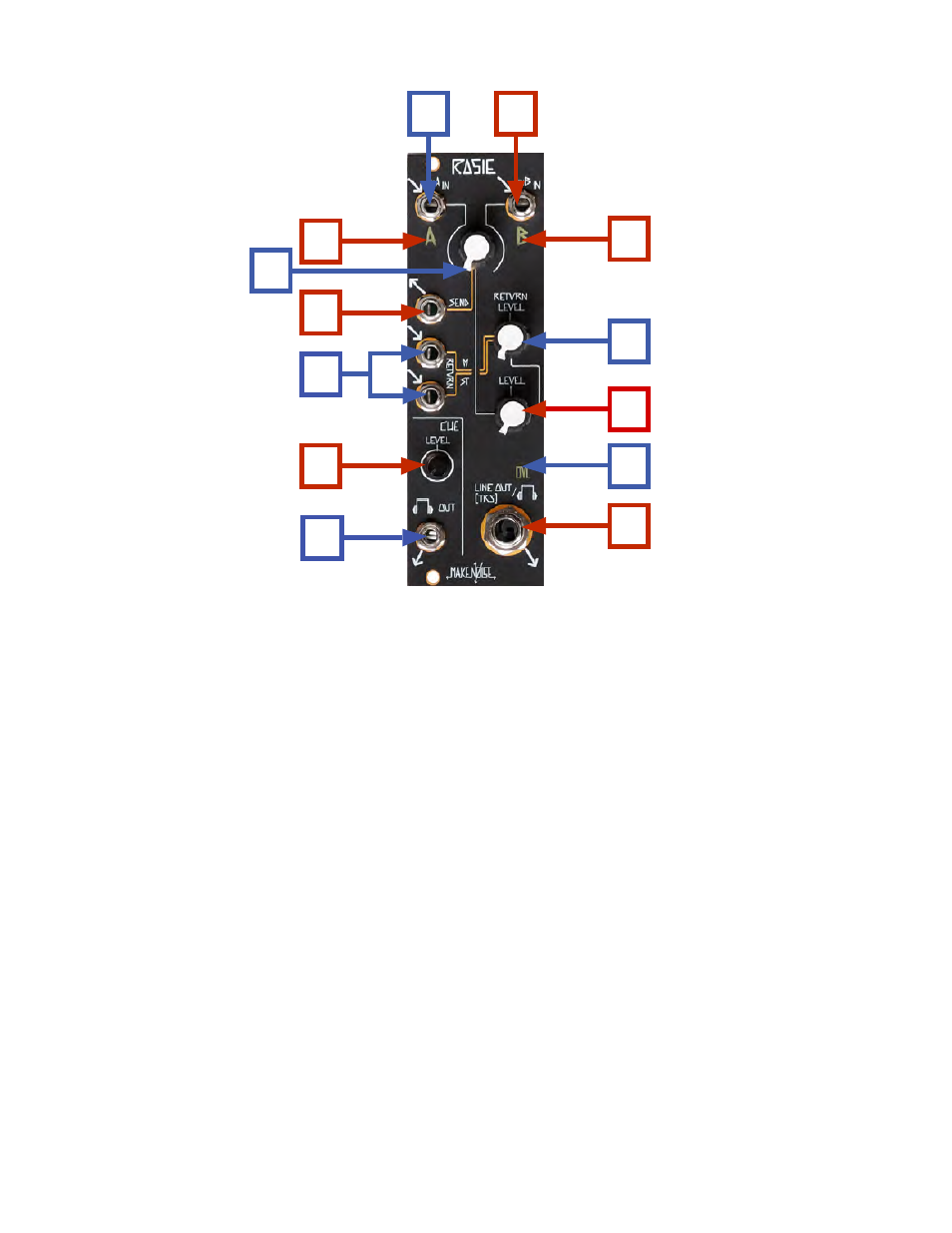
Rosie Panel Connections
1. Channel A Signal Input: expects typical 10Vpp Audio signal from Modular System. AC coupled.
2. Channel B Signal Input: expects typical 10Vpp Audio signal from Modular System. AC coupled.
3. Channel A Level Indicator: LED lights to show strength of signal patched to Channel A input.
4. Channel B Level Indicator: LED lights to show strength of signal patched to Channel B input.
5. Crossfader: selects between Channel A and B or some combination of A and B to be sent to FX Send
and Master Line Out.
6. FX Send output: Mono 10Vpp Audio signal intended to be patched into the Modular System. Also
possible to use with external Line Level devices if attenuation is applied.
7. FX Return input(s): operates as Mono (use only top jack, marked M) or Stereo (use both Jacks marked
M and ST) return for the FX Loop. Expects typical 10Vpp Audio signal from Modular
System. AC coupled. May be used with Line Level devices as well (set Return Level
to Max and adjust output volume at external device).
8. Return Level: manually operated panel control to set the Level of the FX Loop Return in the Master
Output. Range of 0% to 120%
9. Master Level: Sets the volume of the Master Line Out.
10. OVerLoad indicator: OVL lights when signal Level is too high.
11. Master Line OUT: 1/4" TRS jack wired as Stereo output. Low output impedance (60 ohms) allows
this output to drive Headphones as well as Line Level inputs.
12. CUE Level: Sets volume of the signal for CUE Headphones OUT.
13. CUE Output: TRS Mini-Jack wired as MONO. Low output impedance (30 ohms) allows this output
to drive Headphones, as well as Line Level inputs.
1
2
3
6
7
12
5
4
8
10
11
13
9