Operation-hydraulic landing gear – Lippert Components Xl Hydraulic Slideout And Hydraulic Landing Gear (hlg) System User Manual
Page 11
OPERATION-HYDRAULIC LANDING GEAR
WARNING
FAILURE TO ACT IN ACCORDANCE WITH THE FOLLOWING MAY
RESULT IN SERIOUS PERSONAL INJURY OR DEATH.
ALWAYS MAKE SURE THAT THE LANDING GEAR AREA IS CLEAR OF
PEOPLE AND OBJECTS BEFORE AND DURING OPERATION OF THE
LANDING GEAR.
ALWAYS KEEP AWAY FROM THE LANDING GEAR WHEN THE SYSTEM IS
BEING OPERATED. SERIOUS PERSONAL INJURY OR DEATH MAY OCCUR.
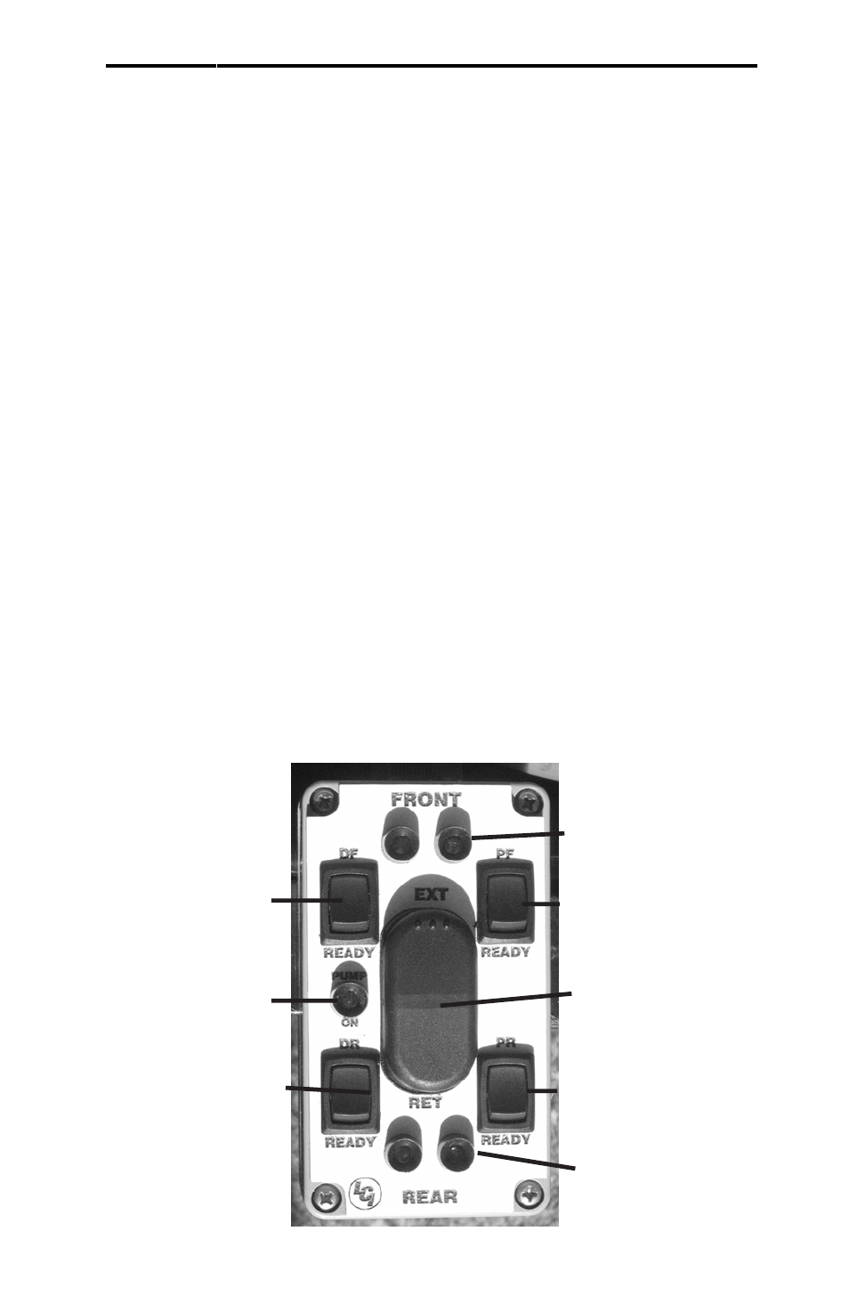
The Lippert XL Hydraulic Slideout and HLG System employs a system of
manually leveling the unit. The control box for the leveling system is located in
the compartment with the pump and works on a remote harness operated from
the outside of the unit. Fig. 5a is the ON/OFF switch making the Control Box
active. Figs. 5b are the switches, when in the “READY” position, correspond with
the leveling jacks to activate the leveling jack. Figs. 5c display the lights that
inidicates which jacks are actve. Fig. 5d is the Master Control switch, extending
and retracting the jacks.
Utilize a carpenter’s level when leveling the unit. Set the level on the floor and
take note of the position of the bubble in both the front to back reading and the
side to side reading. It is best to set up the unit on the most level site available.
The system is set up to level the unit from front to back so it is important to get
the unit as level as possible side to side prior to using the landing gear.
FIG. 5 - LEVELING CONTROL PANEL
11
5b
5c
5d
5c
5b
5a
5a
5a