LAARS Mini-Therm JVi - Install and Operating Manual User Manual
Page 14
Mini-Therm JVi
Page 13
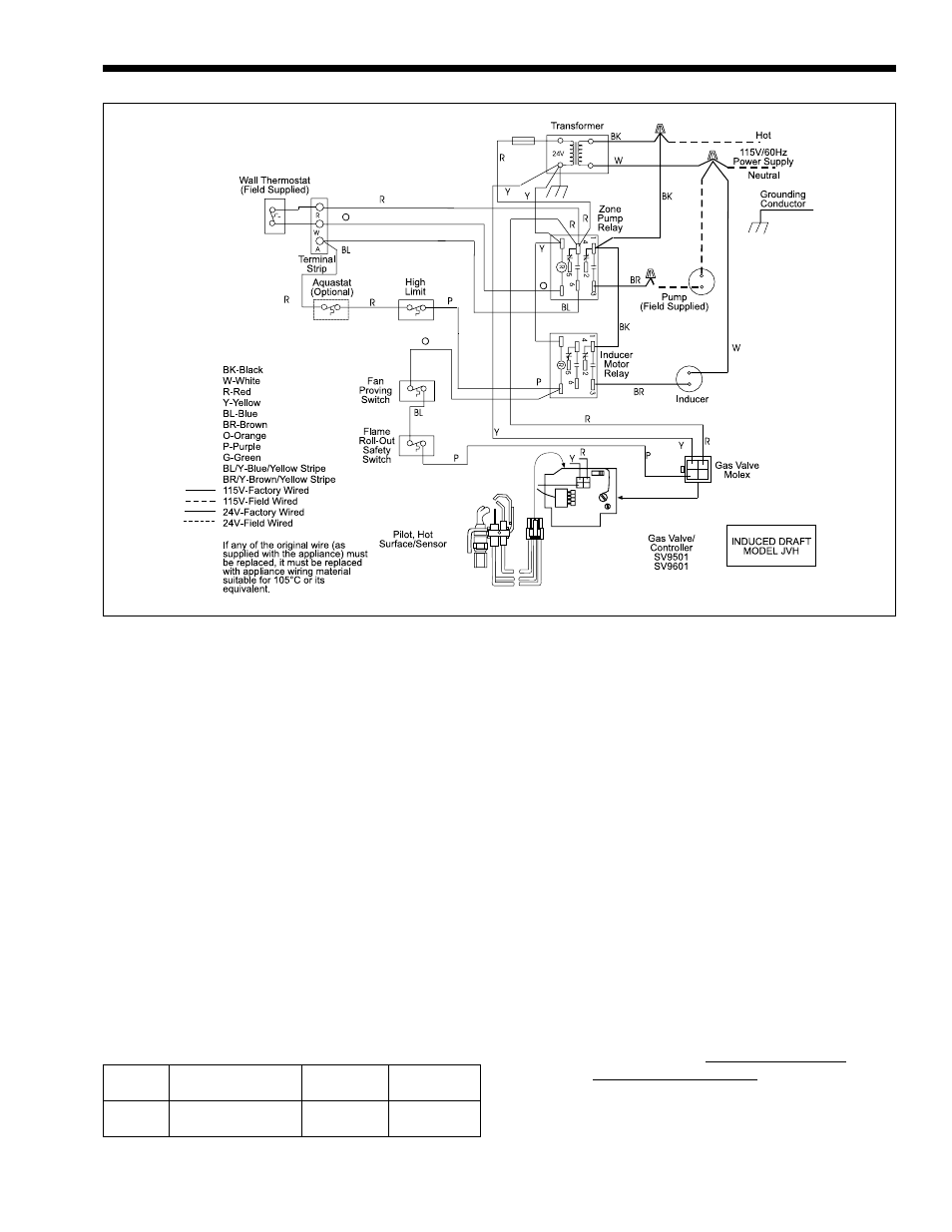
Figure 10. Wiring Diagram, JVH.
12.
Close the water makeup valve and check the
strainer in the pressure reducing valve for
sediment or debris. Reopen the water makeup
valve.
13.
Verify system pressure with the boiler pressure
gauge before beginning regular operation.
14.
Within 3 days of start-up, recheck and bleed all
air vents and the expansion tank using these
instructions.
SECTION 2.
Operating Procedures
Before placing the boiler in operation, check and
reset the safety shutoff devices. Once the boiler is
connected to the gas and water piping and after all the
requirements in previous pages have been met, follow
these procedures:
Boiler
Firing Systems
Valve
Manufacturer
Size
Natural or Propane
Number
50-225
Hot Surface Pilot,
SV9500 &
Honeywell
JVH
SV9600
2A. System Start-up
1.
Verify that the pump system is operating
properly:
a.
Shut off the manual gas valve located
outside the boiler.
b.
Raise the wall thermostat high enough to
call for heat.
c.
The pump should come on immediately. If
it does not, test the electrical circuits.
2.
Pilot and Main Burner Lighting:
a.
The JVH boiler does not require manual
lighting. The pilot is controlled by the
automatic ignition system.
b.
Different models of the JVi boiler utilize
various gas valves, (see Table 11).
Although the gas valves may have different
control knobs, they are all similar in
operation.
c.
Understand and follow the operating
instructions, on page 14, that are applicable
to the type of ignition system installed on
the boiler.
3.
The pilot and main burners will automatically
ignite when there is a call for heat.
Table 11. Gas Valve Identification.