LAARS Mighty Therm2 MT2V (Sizes 500–2000 MBTU/h) - Install and Operating Manual User Manual
Page 27
Mighty Therm
2
Page 27
the highest point in the circulating loop, then the
system is ready for operation.
14. Refer to local codes and the make-up water valve
manufacturer’s instructions as to whether the
make-up water valve should be left open or closed.
15. After placing the unit in operation, the ignition
system safety shutoff device must be tested. First,
shut off the manual gas valve, and call the unit
for heat. After the pre-purge and ignitor heat-up
time, the main gas terminals will be energized,
attempting to light, for four (4) seconds, and then
will de-energize. The unit will go into lockout
mode. Second, turn the power off and then on
again, open the manual gas valve and allow the
unit to light. While the unit is operating, close the
manual gas valve and ensure that power to the main
gas valve has been cut.
16. Within three (3) days of start-up, recheck all air
bleeders and the expansion tank as described in
Steps 4 and 8
above.
Important: The installer is responsible for identifying to
the owner/operator the location of all emergency shutoff
devices.
WARNING
Do not use this appliance if any part has been under
water. Immediately call a qualified service technician
to inspect the appliance
If there is a subsequent loss of flame signal, the burner
will attempt re-ignition up to three times (only once
if optional lockout ignition is used.) When the call for
heat is satisfied, the gas valves(s) close and the blowers
continues to run for 30 seconds.
The pump will continue to run for 0.1 to 10 minutes,
depending on what the pump time delay has been set
to. Mighty Therm2 sizes 1,000-2,000 have two ignition
controls that control the individual stages. If one ignition
control should fail for any reason, the remaining module
can operate its burners independently. (Note that if a
single blower is disabled on units 1250-2000, the other
fan will continue to operate and safely allow the boiler
to run with a single stage.)
6.2 Filling the System
1. Ensure the system is fully connected. Close all
bleeding devices and open make-up water valve.
Allow system to fill slowly.
2. If make-up water pump is employed, adjust
pressure switch on pumping system to provide a
minimum of 12 psi (81.8 kPa) at the highest point
in the heating loop.
3. If a water pressure regulator is provided on the
make-up water line, adjust the pressure regulator
to provide at least 12 psi (81.8 kPa) at the highest
point in the heating loop.
4. Open bleeding devices on all radiation units at the
high points in the piping throughout the system,
unless automatic air bleeders are provided at such
points.
5. Run system circulating pump for a minimum of 30
minutes with the boiler shut off.
6. Open all strainers in the circulating system, check
flow switch operation, and check for debris. If
debris is present, clean out to ensure proper circula-
tion.
7. Recheck all air bleeders as described in Step 4.
8. Check liquid level in expansion tank. With the
system full of water and under normal operating
pressure, the level of water in the expansion tank
should not exceed ¼ of the total, with the balance
filled with air.
9. Start up system according to the procedure in this
manual. Operate the entire system, including the
pump, boiler, and radiation units for one (1) hour.
10. Recheck the water level in the expansion tank. If
the water level exceeds ¼ of the volume of the
expansion tank, open the tank drain, and drain to
that level.
11. Shut down the entire system and vent all radiation
units and high points in the system piping, as
described in
Step 4
.
12. Close make-up water valve and check strainer in
pressure reducing valve for sediment or debris from
the make-up water line. Reopen make-up water
valve.
13. Check gauge for correct water pressure and also
check water level in the system. If the height
indicated above the boiler insures that water is at
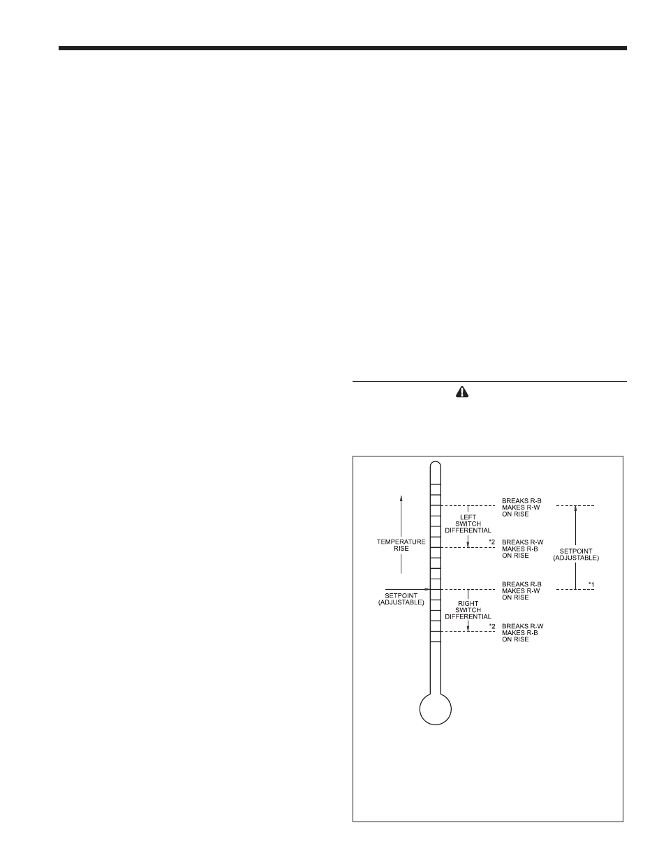
*
1 Difference between the temperatures at which the two switch-
es make R-W. Adjustable from 3°F to 10°F (1.7°C to 5.6°C) on
standard models, or from 3.6°F to 12°F (2.0°C to 6.7°C); 55°F to
175°F (13°C to 79°C) models.
*
2 Two DPDT switches operate in sequence. Each switch differ-
ential is fixed at approximately 3°F (1.7°C) on standard models, or
3.6°F (2.0°C); 55°F to 175°F (13°C to 79°C) models.
Figure 22. Honeywell L8008G.