2 connecting the power, 3 connecting to monitors, 1 bnc connection – KGUARD Security BR1601 User Manual
Page 19: English chapter 2: installation, Dvr user’s manual 19, Channel dvr / 8-channel dvr 16-channel dvr, D+ d, 12v power adapter wall outlet, Monitor, Monitor bnc cable bnc cable
ENGLISH
Chapter 2: Installation
DVR User’s Manual
19
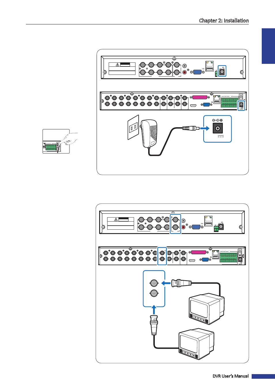
2.2 Connecting the Power
Use only the supplied power adapter that came with the DVR.
1
Connect one end of the power
adapter to the power connector
on the back of the DVR.
2
Plug the other end of the power
adapter into the wall outlet.
3
For 4-channel/8-channel
models, the DVR automatically
powers on.
For a 16-channel DVR, press
the Power switch to turn on the
power.
RS-485
3
4
1
2
1
2
VIDEO
OUTPUT
7
8
5
6
VIDEO INPUT
AUDIO
OUTPUT
AUDIO
INPUT
VGA
12V
LAN
CAUTION
RISK OF ELECTRIC SHOCK
DO NOT OPEN
CAUTION: TO REDUCE THE RISK OF ELECTRICAL SHOCK.
DO NOT OPEN COVERS. NO USER SERVICEABLE
PARTS INSIDE. REFER SERVICING TO QUALIFIED
SERVICE PERSONNEL.
WARNING: TO PREVENT FIRE OR SHOCK HAZARD. DO NOT
EXPOSE UNITS NOT SPECIFICALLY DESIGNED FOR
OUTDOOR USE TO RAIN OR MOISTURE.
VGA
AUDIO IN (CH5-CH16)
HDMI
LAN
1
2
AUDIO OUT
VIDEO OUT
AUDIO IN
2
4
1
3
MAIN
SPOT
CH8
CH16
CH7
CH15
CH6
CH14
CH5
CH13
CH4
CH12
CH3
CH11
CH2
CH10
CH1
CH9
G
1
2
3
4
5
6
7
8
9
10 11
+
-
NO COM G
16 15 14 13 12
RS-485
D+ D-
KB
OUT
IN
ALARM
12V
12V
Power adapter
Wall outlet
4-Channel DVR / 8-Channel DVR
16-Channel DVR
2.3 Connecting to Monitors
The preview screen can be displayed on monitors via BNC, VGA or HDMI (16-channel) connection.
2.3.1 BNC Connection
Connect the video output of
the DVR to the monitor via BNC
connector as shown.
RS-485
3
4
1
2
1
2
VIDEO
OUTPUT
7
8
5
6
VIDEO INPUT
AUDIO
OUTPUT
AUDIO
INPUT
VGA
12V
LAN
CAUTION
RISK OF ELECTRIC SHOCK
DO NOT OPEN
CAUTION: TO REDUCE THE RISK OF ELECTRICAL SHOCK.
DO NOT OPEN COVERS. NO USER SERVICEABLE
PARTS INSIDE. REFER SERVICING TO QUALIFIED
SERVICE PERSONNEL.
WARNING: TO PREVENT FIRE OR SHOCK HAZARD. DO NOT
EXPOSE UNITS NOT SPECIFICALLY DESIGNED FOR
OUTDOOR USE TO RAIN OR MOISTURE.
VGA
AUDIO IN (CH5-CH16)
HDMI
LAN
1
2
AUDIO OUT
VIDEO OUT
AUDIO IN
2
4
1
3
MAIN
SPOT
CH8
CH16
CH7
CH15
CH6
CH14
CH5
CH13
CH4
CH12
CH3
CH11
CH2
CH10
CH1
CH9
G
1
2
3
4
5
6
7
8
9
10 11
+
-
NO COM G
16 15 14 13 12
RS-485
D+ D-
KB
OUT
IN
ALARM
12V
VIDEO OUT
MAIN
VIDEO OUT
SPOT
Monitor
Monitor
BNC cable
BNC cable
4-Channel DVR / 8-Channel DVR
16-Channel DVR
LAN
G
1
2
3
4
5
6
7
8
9
10
11
+
-
NO COM
G
16
15
14
13
12
RS-485
D+
D-
KB
OUT
IN
ALARM
12V