Intrepid multi-fuel clearance diagrams, Protected surfaces unprotected surfaces – Vermont Casting 1695 User Manual
Page 14
14
Vermont Castings Intrepid Multi-Fuel
2000970
D
E
F
F
C
C
A
B
J
K
L
L
I
I
G
H
ST507
Intrepid Clearance
Diagrams
11/00
P
Q
M
N
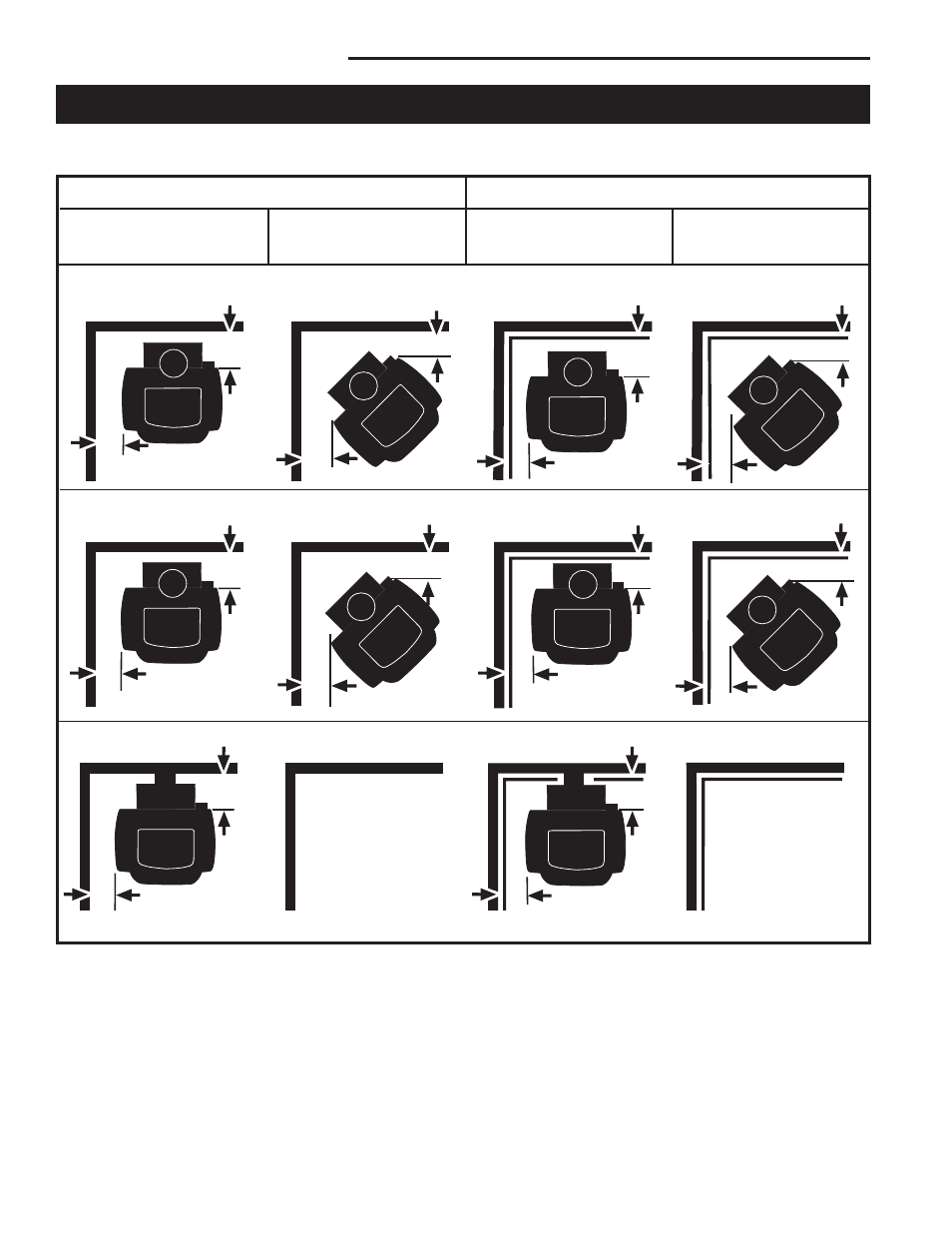
Intrepid Multi-fuel Clearance Diagrams
See the chart on Page 13 for dimensions indicated by letter in the diagrams below.
Stove Installed
Parallel to Wall
Stove in
Corner
Stove in Cor-
ner
Stove Installed
Parallel to Wall
Protected Surfaces
Unprotected Surfaces
Top Exit Installations, no heat shields
Top Exit Installations, rear heat shield, and chimney connector heat shields or double-wall connector
Rear Exit Installations, rear heat shields.
ST507
N/A
N/A