Vermont castings intrepid multi-fuel, Fireplace and mantel trim shields – Vermont Casting 1695 User Manual
Page 11
11
Vermont Castings Intrepid Multi-Fuel
2000970
In top-exiting installations in which the single-wall con-
nector extends to the ceiling and connects to a prefab-
ricated insulated metal chimney, the connector shield
must extend to within an inch of the ceiling. A ceiling
heat shield must be installed that is 22” (560 mm) in
diameter and, as explained above, that extends 1”
(25 mm) below the ceiling. The ceiling shield must be
constructed of 24 gauge or heavier sheet metal, must
be centered on the chimney, and must meet any wall
protector that is also a part of the installation.
The Intrepid Multi-Fuel has not been tested with double-
wall connectors and wall heat shielding. Maintain 12”
(305 mm) clearance around double-wall chimney
connectors. No further clearance reduction is per-
mitted.
Fireplace and Mantel Trim Shields
A fireplace installation requires special clearance be-
tween the side of the stove and the right and left walls,
between the side of the stove and the decorative side
trim on the fireplace face, and between the top of the
stove and the mantel.
Noncombustible shields installed 1” (25 mm) away from
the combustible surface on noncombustible spacers,
called ventilated shields, may be used to reduce clear-
ances. (Fig. 13)
To protect a mantel from the heat of an Intrepid Multi-
fuel in a fireplace installation, the ventilated mantel
shield must be at least 48” (1219 mm) long, and it must
be centered over the stove. Ventilated shields for side
trim must extend the full length of the trim.
An unprotected mantel (‘A’, Fig. 14) cannot be more
than 9” (229 mm) deep and must have a minimum
clearance of 30” (762 mm), measured from the stove’s
top plate. With a ventilated shield, (Fig. 13) this clear-
ance may be reduced safely to 14” (356 mm).
ST253a
Multi-fuel
trim clearances
1/22/01 djt
C
C
A
B
ST253
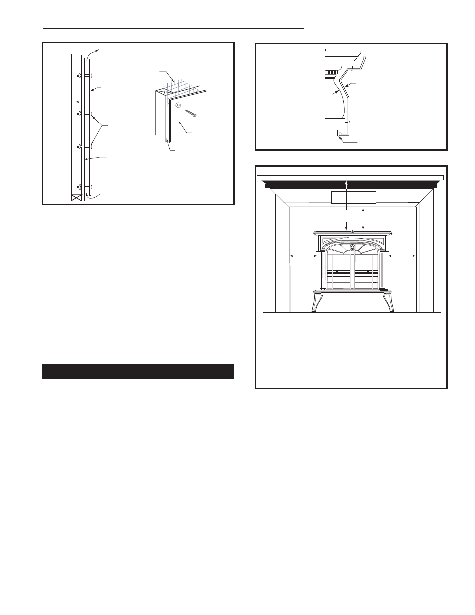
Fireplace Mantel and Trim Clearances
Measured from the top and sides of the stove
A. Mantel
30” (762 mm)
14” (356 mm)
B. Top Trim
24” (610 mm)
14” (356 mm)
C. Side Trim
15” (381 mm)
10” (254 mm)
Unprotected
Protected
Fig. 14 Maintain clearances to combustible components of
the mantelpiece.
1" (25mm)
1/4" (6mm)
ST501
mantel and
trim shield
11/10/00 djt
ST501
Fig. 13 A custom-formed mantel shield.
Unprotected top trim (B) protruding 2” (51 mm) or less
from the face of the fireplace must be a minimum of 24”
(610 mm) from the stove’s top surface. With a venti-
lated trim shield, this clearance may be reduced safely
to 14” (356 mm).
Unprotected side trim (C) that protrudes 2” (51 mm) or
less from the face of a fireplace must have a minimum
clearance of 15” (380 mm), measured from the stove’s
top side edge. With a ventilated trim shield, the clear-
ance may be reduced safely to 10” (254 mm). If the
trim extends more than 2” (51 mm), wall clearance
requirements apply.
The charts and sample installations that follow list the
clearances required for the various installation configu-
rations of the Intrepid Multi-fuel.
Fig. 12 Approved wall shield construction.
ST248
wall shield construction
12/14/99 djt
Air Flow
Stud Wall
Framing
Wall Shield
Noncombus-
tible spacers
and fasteners
Drywall
Air Flow
Shield
Metal Spacer
ST248
Metal
Screening