Intrepid multi-fuel clearance chart, All installations unprotected surfaces, Front clearance to combustibles – Vermont Casting 1695 User Manual
Page 13
13
Vermont Castings Intrepid Multi-Fuel
2000970
Side
Rear
Corners
Side
Rear
Corners
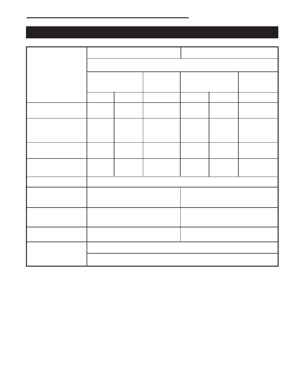
(A) 24”
(B) 30”
(C) 20”
(D) 12”
(E) 16”
(F) 10”
(610 mm) (762 mm)
(508 mm)
(305 mm) (410 mm)
(254 mm)
(G) 24”
(H) 16”
(I) 12”
(J) 12”
(K) 9”
(L) 10”
(610 mm) (410 mm)
(305 mm)
(305 mm) (229 mm)
(254 mm)
(M) 24”
(N) 14”
(NA)
(P) 12”
(Q) 9”
(NA)
(610 mm) (356 mm)
(305 mm) (229 mm)
(G) 24”
(H) 16”
(I) 12”
*
(610 mm) (410 mm)
(305 mm)
Intrepid Multi-Fuel Clearance Chart
See Pages 14 and 16 for illustrations of these clearances.
All Installations
Unprotected Surfaces
Top exit, rear stove h.s.,
single-wall chimney
connector with connector
heat shields
1,2
No stove heat shields
Rear exit, rear stove
heat shield only
3
Top exit, rear stove
h.s., double-wall
chimney connector
5
Single-wall chimney
connector, no
connector heat shields
Single-wall chimney
connector, with
connector heat shields
Double-wall
connector
5
* Clearances with double-wall connectors and protected surfaces have not been tested for the Intrepid.
1. Shielding for a top exit stove must include the stove rear heat shield insert to protect the area behind the flue collar.
2. Chimney connector heat shields, in an installation that goes through a combustible ceiling, must extend to 1” (25 mm) below the
ceiling heat shield, which is 22” (559 mm) in diameter. The ceiling heat shield should be 24 gauge or heavier sheet metal, centered
on the chimney connector, and mounted on non-combustible spacers.
3. Rear exit—horizontal from flue collar directly back through wall.
4. The ceiling heat shield required when chimney connector shields are used should meet the wall protector. This will require trim-
ming the ceiling shield along the line of intersection with the wall protector.
5. In top exit installations, this clearance requires the use of the rear heat shield with the shield insert installed.
Protected Surfaces
Chimney Connector Clearance
Stove Clearance
48” (1219 mm)
Front Clearance to Combustibles
12” (305 mm)
5” (127 mm)
4
10” (254 mm)
26 “ (661 mm)
*
12” (305 mm)
Stove Installed
Stove in
Stove Installed
Stove in
Parallel to Wall
Corner
Parallel to Wall
Corner