Appendix, Configurations of terminals – Christie Digital Systems 38-VIV210-01 User Manual
Page 43
43
APPENDIX
Vcc
- Data
+ Data
Ground
1
2
3
4
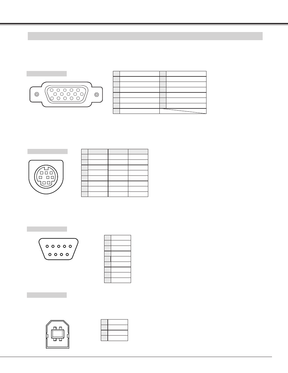
USB PORT TERMINAL
Pin Configuration
Connect USB port output terminal of computer or peripheral equipment to this terminal with USB port Cable (not
supplied).
2
3
4
1
CONFIGURATIONS OF TERMINALS
Terminal : Mini DIN 8-PIN
Connect control port (PS/2, Serial or ADB port) on your computer to this terminal with Control Cable (Not supplied).
1
2
3
4
5
8
7
6
Pin Configuration
CONTROL PORT CONNECTOR
-----
CLK
DATA
GND
-----
-----
GND
-----
R X D
-----
-----
GND
RTS
T X D
GND
GND
-----
ADB
-----
GND
-----
-----
-----
GND
PS/2
Serial
ADB
1
2
3
4
5
6
7
8
-----
RxD
TxD
-----
Ground
-----
-----
-----
1
2
3
4
5
6
7
8
9
-----
1
2
3
4
5
6
7
8
9
Connect serial port output terminal of computer to this terminal with Serial Cable (not supplied).
Pin Configuration
SERIAL PORT IN/OUT TERMINAL
HDB 15-PIN TERMINAL (ANALOG)
Connect display output terminal of computer to this terminal with VGA Cable (supplied).
● When connecting Macintosh computer, use MAC/VGA Adapter (Not supplied).
5
1
2
3
4
10
9
6
7
8
15
14
13
11
12
Red Input
Ground (Horiz.sync.)
Green Input
Sense 2
Blue Input
Ground (Red)
Ground (Green)
Ground (Blue)
1
5
2
4
3
6
7
8
+5V Power
Horiz. sync.
Ground (Vert.sync.)
DDC Data
Sense 0
Vert. sync.
DDC Clock
9
13
10
12
11
14
15
Pin Configuration