Interlogix VDP-MSP Series User Manual
Page 4
4 of 12
P/N 1069680 • REV 1.0 • ISS 14APR10
• DO NOT send Up-the-Coax Pan/Tilt/Zoom signals through active (amplified)
GE transmitters or receivers. Passive GE transceivers can transmit video and
Up-the-Coax P/T/Z control signals up to 750 ft. (228 m).
• We recommend using short 18 AWG solid wires for ground connections.
• GE VPD products follow the EIA/TIA 568 standard. There are two wire color-
code standards: EIA/TIA 568A and EIA/TIA 568B. Either standard can be used
for making connections as long as the RJ-45 jacks at both ends of each
cable follow the same standard.
• Measure wire distance by:
1. Shorting the two conductors together at the far end, and measuring
the loop-resistance by an Ohmmeter.
2. Use
the
Loop Resistance table to calculate the distance.
• DO NOT connect coax cables longer than 100 ft. (30 M) to the BNC
connectors of any GE UTP equipment.
• All measured distances should include any coax cables in the path.
• Verify camera current requirements and wire resistance limits for the
maximum distance that power can travel. Use the Power Distance Chart to
verify the wire distance.
• GE VPD products require Unshielded Twisted-Pair (UTP) wires Category 2 or
better, 24 AWG (0,5 mm) or thicker.
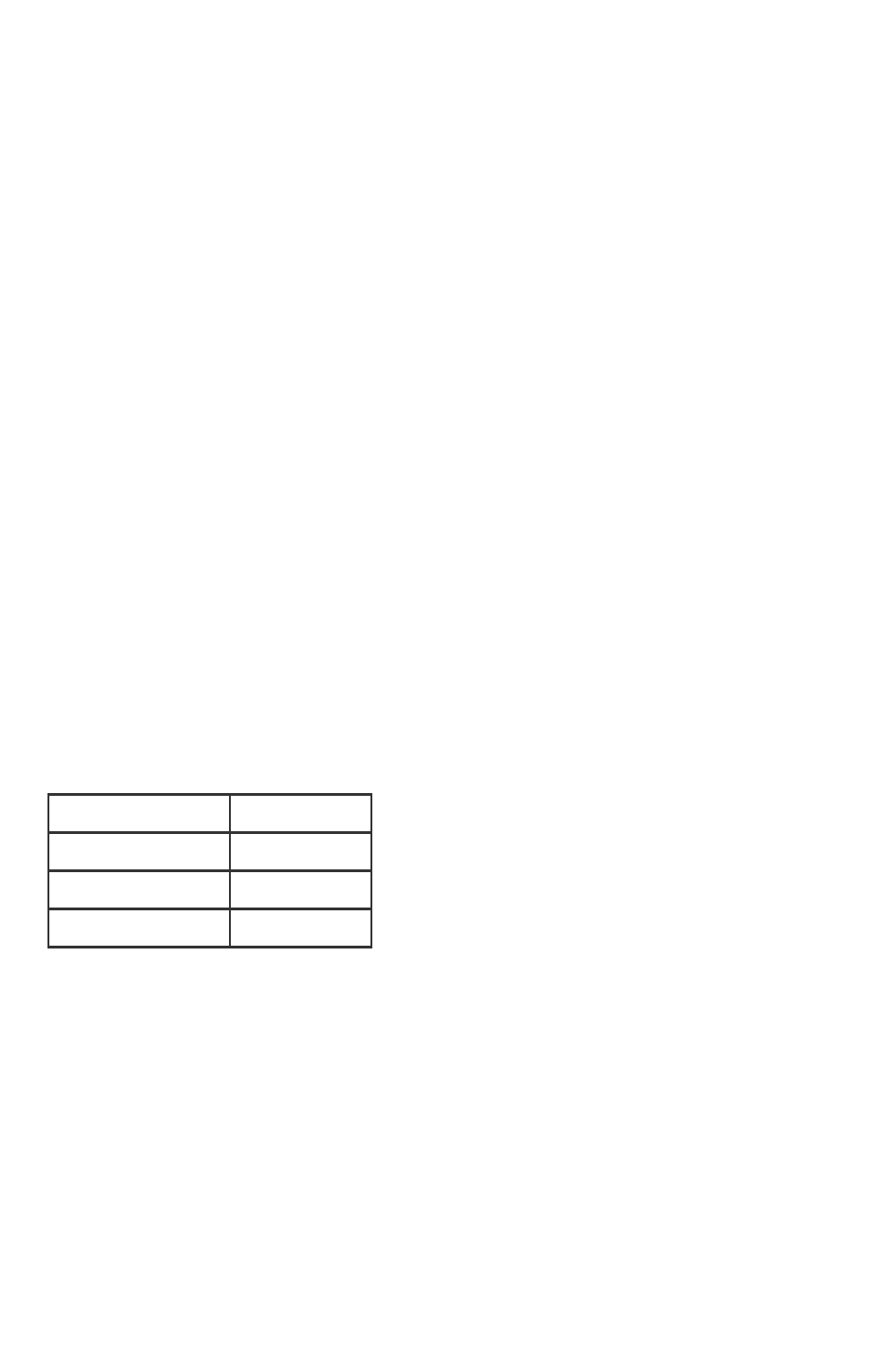
Table 1: Loop Resistance per 1000 feet
Wire Type
Resistance
24 AWG /0,53 mm
52 ohms
23 AWG /0,57 mm
42 ohms
22 AWG /0,64 mm
33 ohms