Mounting installation, Mounting to a din-rail, Mounting installation 9 – Interlogix NS2051-4P/1T User Manual
Page 13
IFS MC251-4P/1S and NS2051-4P/1T User Manual 9
Note:
The wire gauge for the terminal block should be in the
range between 12 ~ 24 AWG.
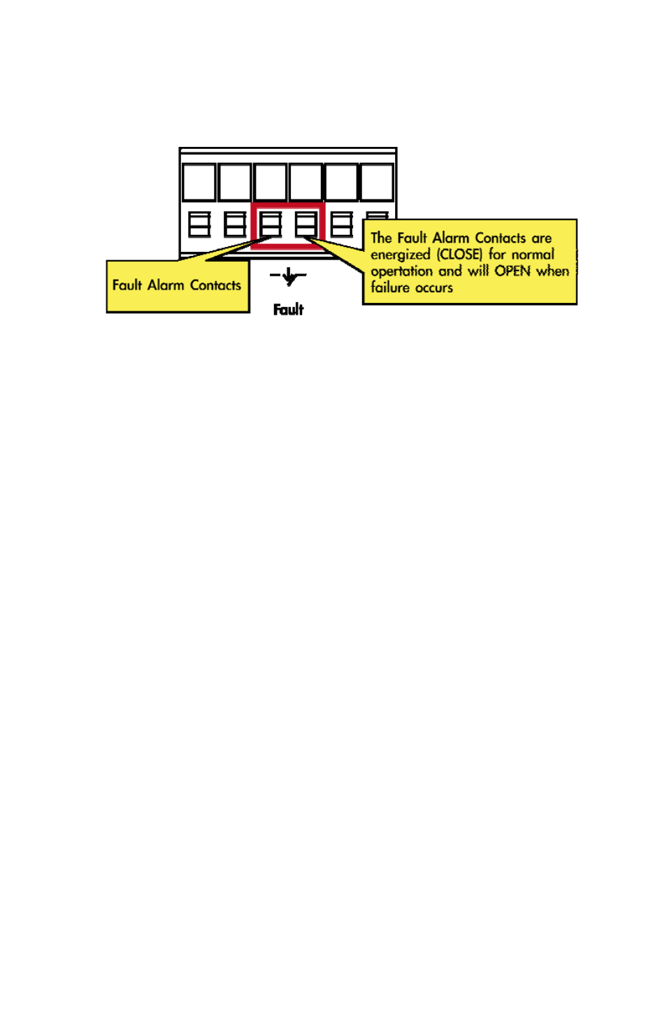
The alarm relay circuit accepts up to 30V, max. 3A currents.
Mounting Installation
This section describes how to mount the MC251-4P/1S and
the NS2051-4P/1T and make connections to it. Please read
the following sections and perform the procedures in the order
presented.
Note:
In the installation steps below, this Manual uses the IFS
GE-DSGH-8 Industrial Gigabit Switch as an example.
However, the steps for any IFS Industrial Switch & Industrial
Media Converters are similar.
Mounting to a DIN-Rail
The DIN-Rail kit comes assembled on the MC251-4P/1S and
the NS2051-4P/1T out of the box. Please refer to following
figures to hang the MC251-4P/1S and the NS2051-4P/1T on a
DIN-Rail.