3 bidirectional talk, 4 alarm setup – IC Realtime 3.0 MegaPixel 3.3-12mm VF IR Vandal IP Dome with SD & POE (ICIP3000DVIR) User Manual
Page 19
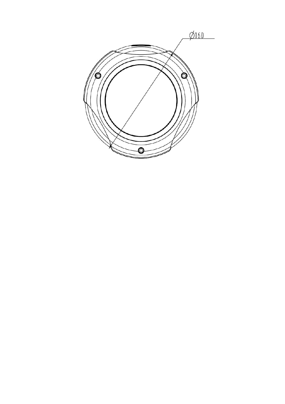
Figure 2-3
2.3 Bidirectional talk
2.3.1 Device Connection
Before the operation, connect the active pickup to the audio input port of the device. Connect the
active speaker to the audio output port of the device. Please make sure the client-end device has the
audio input and output function. For example, you need to connect the microphone and then
earphone to the PC if you want to implement the bidirectional talk function.
2.3.2 Operation
Login the Web and click the bidirectional talk button to enable this function. Click this button again; you
can close current bidirectional talk.
2.4 Alarm Setup
The alarm interface is shown as in Figure 2-4. Please follow the steps listed below for local alarm input
and output connection.
1) Connect the alarm input device to the alarm input port (grey or brown pin of I/O port cable).
2) Connect the alarm output device to the alarm output port (White-pin) and alarm output public
port (Red-pin). The alarm output port supports NO (normal open) alarm device only.
3) Open the Web, go to the Figure 2-4. Please set the alarm input 01 port for the brown-pin (the
1
st
channel) of I/O port cable. The alarm input 02 is for the grey-pin (the 2
nd
channel) of I/O port
cable. Then you can select the corresponding type (NO/NC.)
4) Set the WEB alarm output. The alarm output port of the alarm output 01 device (The white-pin of the
I/O port cable).
13