I.C.E. GIDM-325 User Manual
Page 6
5
5. Lubricate (if necessary) the burner, induced draft fan and main fan motors. The specifications on
the motors for grease and oil shall be adhered to.
6. Check heater outlets and exhauster, or induced draft discharge for obstructions.
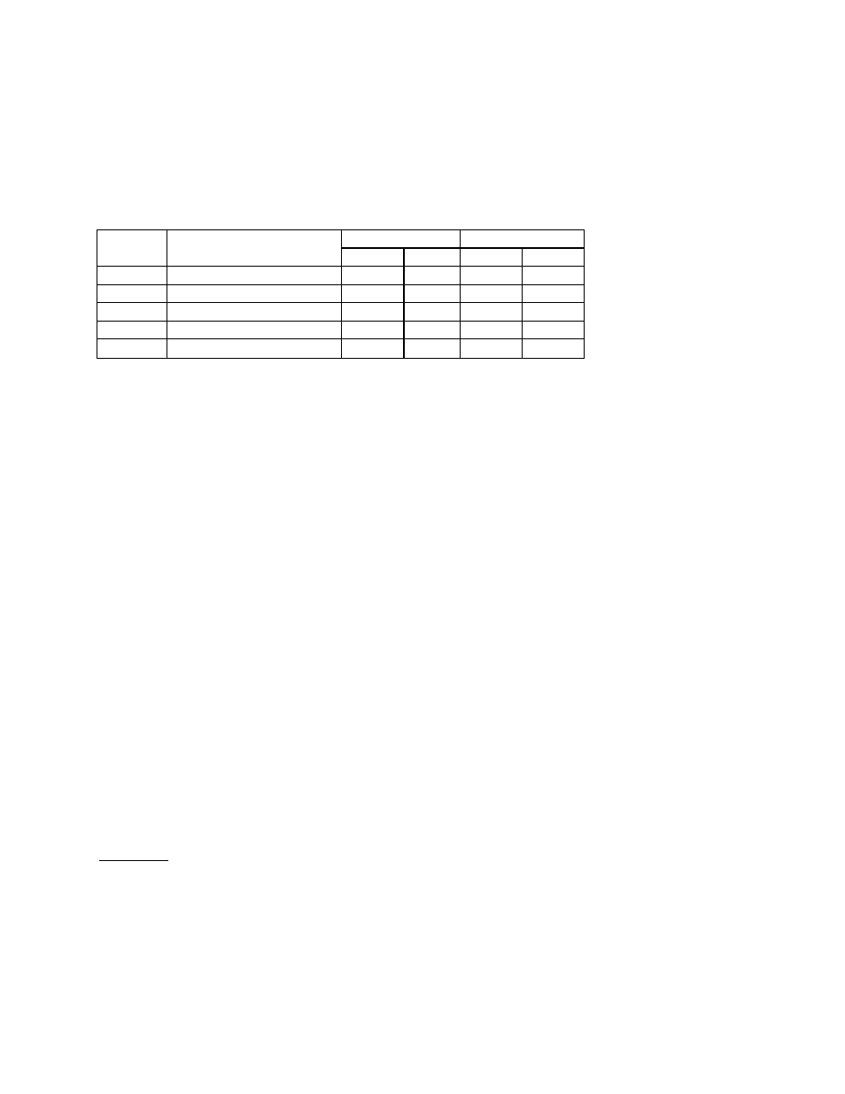
7. Check fan-limit control. Setting should be as follows:
MODEL
CONFIGURATION
MAIN
AUXILIARY
LIMIT
FAN*
LIMIT
FAN*
C
Horizontal Suspended
240
120
NA
NA
D
Vertical Upflow Floorset
180
80
NA
NA
R
Vertical Downflow Floorset
180
80
165
100
M
Horizontal Floorset
240
120
NA
NA
AC
Vertical Upflow Floorset
180
80
NA
NA
*Fan “ON” settings, set differential for Fan “OFF” 15-20 degrees below fan setting.
8. Ensure that the flue is in place and providing proper overfire draft as noted in previous section on
“Connecting the Flue”.
9. The induced draft proving switch (power vented units only) is factory set and must not be tampered with. This
switch will not allow unit operation if overfire draft is outside of the acceptable operating range.
10. Check all fuse blocks to determine that all fusing is installed.
11. Set the operating controls (eg. thermostat, remote panel switches) so as to allow heating
operation of the unit.
12. Reset the primary flame safeguard by pushing the reset button or lever.
13. Reset motor starter by pushing the reset button, if so equipped.
14. Check building system gas supply and be sure all lines are purged of air.
15. Check building system gas supply pressure.
CAUTION - GAS UNITS
At maximum input the gas pressure must fall within the range specified on the unit rating plate.
Optional high and low gas pressure switches (if supplied) must be reset.
16. Check all piping for tightness and correct any signs of leaks.
WARNING: Fire or explosion hazard can cause property damage, severe injury, or death. Check for gas
leaks with rich soap and water solution any time work is done on a gas line. Never use an open
flame to detect gas leaks.
START-UP
1. Refer to factory test report for correct settings that are to be checked on the unit.
2. Check the supply fan motor thermal overload setting against the rating plate figure.
3. Ensure burner on-off switch is “off”. (On heating units using a fan plenum switch, jumper the fan switch).
4. Put the main disconnect switch in the “on” position, thus activating the supply fan. Check for correct direction
of rotation.