Haltech HT053009 User Manual
Page 7
ECU Manager Software
ECU Manager software is used for setup, calibration and diagnostics and can
be found on the CD supplied with this unit or downloaded from the Haltech website
www.haltech.com
Minimum System Requirements
Operating System:
Windows 2000 SP4 / XP / Vista / Windows 7
Processor Speed:
1GHz
RAM:
256 Mb
Video Card:
128MB graphics card with 3D acceleration
USB:
1.1
Hard Drive Space:
250Mb
Minimum Screen Resolution:
1024 x 768 pixels
Installing ECU Manager
Installing ECU Manager onto your PC is performed similar to any other Windows
software package. Installation is outlined below to ensure correct installation:
1.Insert the CD-ROM into your PC’s CD-ROM drive. The CD should automatically
launch into the Haltech Browser. If the CD does not run automatically double
click on the “My Computer” icon on the desktop, double click on the Haltech icon
(CD- ROM drive) to start the browser software.
2.The Browser will display the disclaimer and you will need to agree to the
terms stated before allowing to progress. Read the Disclaimer and click on
AGREE if you agree.
3.Now you will be able to access all the information contained on the CD
4.To download the Platinum Software, click on the Platinum Series ECU Manager
Link. You will be prompted to install the software. Click “Install” to install
ECU Manager and the Data Log viewer.
5. Follow the software prompts and install the software.
With your programming cable (USB) attached to your ECU and the other end
connected to your laptop, power up the ECU by turning your key to IGN. Start the
programming software on your PC and go online with the ECU.
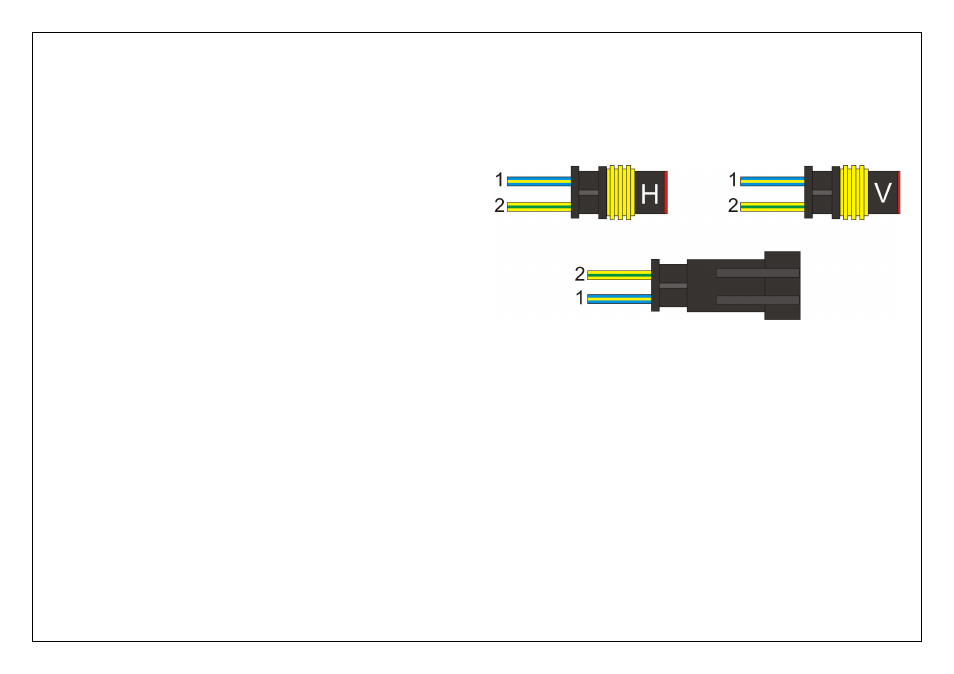
The CAN Intercept Connectors
The Platinum Pro R35 GT-R ECU is capable of communicating with the vehicles
on board CAN Bus. These connectors are used for Haltech development only.
The Connectors labeled as “Haltech CAN” and “CAN BUS” Must always be
connected together, whilst the connector labeled “Vehicle CAN” must remain
disconnected.
Figure 6 – CAN Intercept connectors