Haltech HT053009 User Manual
Page 10
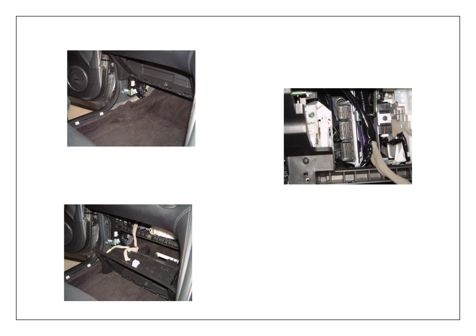
4.
Remove the passenger side kick panel and skirt.
Remove the skirt first by gently lifting it up. This skirt is only held in by clips.
Remove the kick panel by removing the plastic nut on the firewall securing it in place,
once undone the kick panel can be removed.
Figure 10 – Kick panel and skirt removed
5.
Remove the inner glove compartment cover.
To do this remove the 7 Phillips head screws holding it in place. Once all seven screws
have been removed the cover should come out. You will then need to disconnect the
two connectors on the back of this cover for the internal light and the boot release
switch.
Figure 11 – Glove compartment inner cover removed showing wiring connectors
6.
Remove the factory ECU
You should now be able to see the factory ECU. To remove it disconnect the 3 header
plugs connected to it. Proceed to undo the 2 x M10 bolts securing the factory mounting
bracket in place. One is located above the ECU and the other is located below the ECU
on the firewall. Cut the cable tie holding the main wiring harness and the mounting
bracket should be able to be moved down making it accessible to now remove the
suspension ECU. Undo the 2 x M10 Bolts securing the Suspension ECU to the bracket.
Once removed relocate/ remount the Suspension ECU up out of the way by means of
cable ties. Relocate the baro sensor under the dash. Mount with a cable tie.
Figure 12 – Factory ECU with header plugs removed