Haltech HT051462 User Manual
Page 5
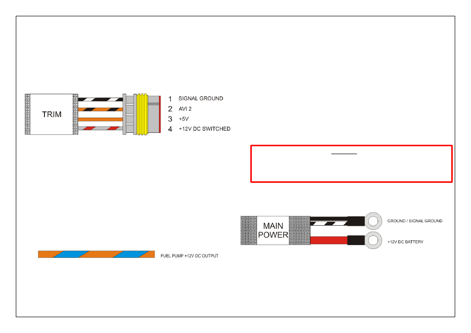
Trim Module Connector
The Trim Module connector can be used in conjunction with the optional
Haltech Trim Module ( #HT010502) to make quick manual adjustments to
the Boost level / Fuel Injection Times and Ignition Timing depending on software setup.
Only one option can be adjusted at any one time with the single Haltech Trim Module.
Alternatively this connection uses Analogue Voltage Input 2 (AVI2) which can be
used / wired as a standard function input if required.
Figure 7- Trim Module Connector Pinout
Fuel Pump Output (O/L)
Fuel Pump Output supplies a continuous +12V DC supply to the fuel pump when the
engine is running. This output wire is rated for a max continuous current draw of 15A .
The Fuel Pump Output wire can be connected directly to the positive side of the fuel
pump, providing the pump in use will draw less than 15A of current under full load.
If your pump will draw more than 15A or if dual pumps are to be used it is
recommended that you use this wire to control a relay to turn on the fuel pumps.
Figure 8 - Fuel Pump Output Wire, 15A Max Continuous Current
Harness Connections
Main Power
The main power connections are located in the harness next to the starter motor.
Battery + ( R )
The Battery + (Red) connection will supply the 12V DC to the harness.
Please connect this cable directly to the starter motor 12VDC Battery + Supply lug.
Ground ( B ) / Signal Ground ( B/W )
The Ground (Black)/ Signal Ground (Black / White)connection supplies the Ground
and Signal Ground for the harness. The Ground Lug consists of two cables terminated
with the one 10mm ID eyelet. Please connect this cable directly to the Engine block.
WARNING!
Please make sure your engine block is grounded to the chassis of the vehicle by
a correct sized grounding strap. This harness will not ground your engine,
damage can occur to this harness and / or your ECU if your engine is not
properly grounded.
Figure 1 - Main power Connections