Haltech HT051462 User Manual
Page 10
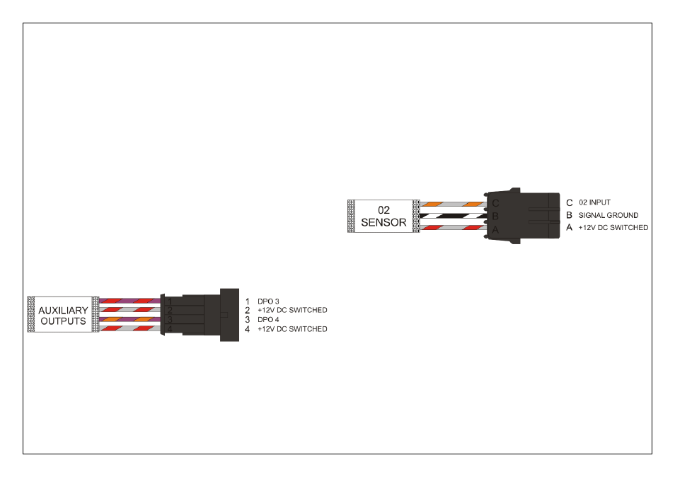
Auxiliary Output Connector
The Auxiliary Output connector contains two Digital Pulsed Outputs (DPO 3 & DPO 4),
and two +12V DC Switched Power connections.
When the output is activated by the ECU the output will switch to ground.
Solenoid valves and shift lights etc can be run directly from the output, however high
current devices such as thermo fans and additional fuel pumps must be activated
through a relay. A Relay can be wired between the DPO and the supplied +12V DC on
this connector. This way the output is only switching the relay and not a high current
draw device.
The Digital Pulsed Outputs are limited to 800mA Max current draw.
These outputs can be programmed within the ECU Manager Software to control
auxiliaries such as:
•
Air Con Output
•
Aux Fuel Pump
•
Boost Control
•
ECU Diagnostic Light
•
Intercooler Fan
•
Shift Light
•
Thermo fans
For a full list of output options and explanations please go to the help within the
ECU Manager Software.
Figure 3 - Auxiliary Output Connector
02 Sensor Connector
The 02 Sensor connector comprises of the following connections:
02 Input Signal (GY/O)
Connect the output of a Narrowband 02 Sensor or the output of a Wideband Controller
to this connection.
Signal Ground (B/W)
This is a signal ground and can be used for grounding a 3 wire 02 Sensor or a
Wideband 02 Controller.
+12V DC Switched (GY/R)
This is the +12V DC Supply for powering the heater on a 02 Sensor or for powering
the Wideband 02 Controller
Figure 4 - 02 Sensor Connector