Haltech HT045505 User Manual
Page 6
Oil Pressure Sensor (Oil-P)
The Oil-P labeled connector connects directly a Haltech oil pressure sensor.
This will enable the user to know the current oil pressure of the vehicle.
An optional oil pressure sensor must be fitted. Haltech Part # HT010904
Oil Pressure is allocated to Analogue Voltage Input 4 (AVI4) on the Haltech Sport ECU.
OEM Oil Pressure Sensor (Oil-P Switch, Oil-P Gauge)
Provisions have been made in the harness to accommodate the OEM cluster oil
pressure switch and oil pressure gauge. Wires have been run from the gauge to the in
cabin harness labeled Oil-P Switch and Oil-P Gauge. Connect these wires to the OEM
oil pressure sensor and the dash cluster for correct operation of the cluster gauge and
oil pressure light if required. Insulate and isolate if not used.
Camshaft Position Sensor Input (CAM)
The Camshaft Position Sensor is used to determine crankshaft position and stroke of
the engine. Connect this directly to the 4 pin sensor connector located on the distributor.
Throttle Position Sensor (TPS)
The Throttle Position Sensor measures the throttle butterfly rotation.
A Haltech throttle position sensor or similar variable resistance TPS is required to be
fitted to the OEM throttle body for correct operation.
The OEM TPS is not a variable resistance sensor.
Starter Signal (STS)
The Starter Signal connects directly to the starter motor solenoid.
This will supply 12V to the solenoid on receiving a start signal from the ignition switch
when in the start position.
Please ensure you supply a main power connection to the starter motor and a
main earth strap to the engine to ensure correct operation of the starter motor,
and to avoid damage to your terminated harness and ECU.
Alternator (ALT)
The Alternator output connects directly to the OEM Alternator.
The +12V signal and alternator warning light wires are pre-wired into the loom.
Connection of the warning light is required for correct operation of the alternator.
The warning light cable can be found in the in cabin harness, and is labeled as
“Alt Light”. Connect this to the negative side of your warning light from your dash.
Alternatively connect a 470R resistor between the Alt Light and +12VDC Switched
labeled wires in the cabin harness if a warning light is not required.
Please ensure you supply a main power connection to the Alternator
Heavy gauge wire must be used
Fuse Box
The Haltech fuse box is connected to the harness.
Contained within the Haltech Fuse box is 6 fuses and 6 relays, each fuse protects the
corresponding relay output ( ie fuse #1 protects relay ouput #1, fuse #2 protects relay
output #2 etc).
The Haltech fuse box can handle a maximum continuous current draw of 70AMP,
exceeding this value may cause damage to the fuse box therefore please ensure all
auxiliary devices, fans and fuel pumps connected do not exceed the supplied fuse
current limits.
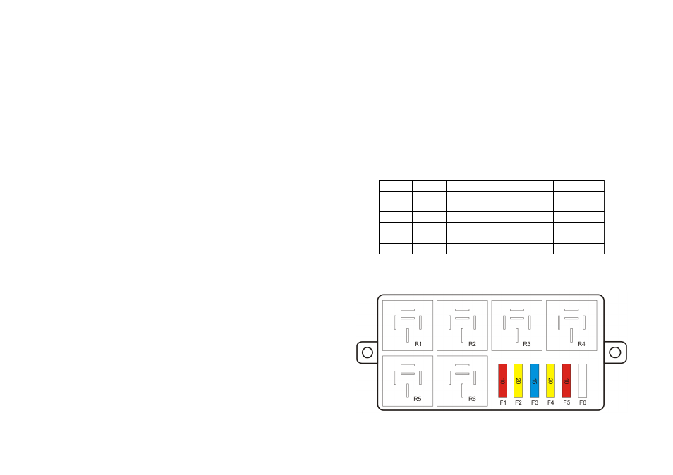
The functions of each of the relays are outlined below:
Figure 4 – Haltech fuse box relay allocation table
Figure 5 – Haltech fuse box layout
Fuse #
Relay #
Function
Fuse Required
F1
R1
+12V Output to ECU
10A
F2
R2
+12V Output to Injectors
20A
F3
R3
+12V Output to Ignition
15A
F4
R4
+12V Output to Fuel Pump
20A
F5
R5
+12V Output to Accessories
10A
F6
R6
Unpopulated
-