Char-Broil 463263110 User Manual
Page 23
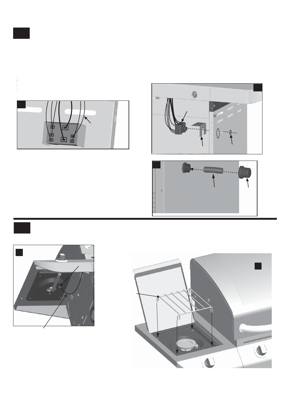
14
15
23
Release the cap and nut from electronic ignition module. Attach electronic ignition module and heat shield to the cart right
back of the electronic ignition module. Total (2) connections, shown A.
electronic ignition module. Total (5) connections. Connect the two wires {(a) and (b)} from the switch wiring harness into the
Inside of cart, connect each of the wires from the main burner electrodes, and sideburner electrode into the back of the
side panel with the nut, shown B.
Insert AA battery into ignition module, negative (
–
) end first. Then put on the cap, shown C.
+
-
ignition module
Electronic
Nut
Cap
wire
NOTE: Switch terminals are larger than electrode
terminals and should only be installed in
location shown as A, B.
AA battery
Right side panel
B
C
1
2
3
(a)
(b)
4
5
A
Heat shield
Under sideburner shelf, attach sideburner ignitor wire to electrode, shown A. Place sideburner grate onto sideburner shelf,
aligning grate legs with holes in shelf, shown B.
A
Sideburner Ignitor Wire
Electrode
Sideburner grate
B
- BIG EASY 4638213 (1 page)
- 463666512 (28 pages)
- INFRARED 8401504 (8 pages)
- 463741209 (32 pages)
- 463420509 (32 pages)
- Patio Caddie 06601295 (20 pages)
- 4984722 (1 page)
- 463257010 (32 pages)
- NATURAL GAS CONVERSION KIT 7116572 (24 pages)
- PATIO BISTRO 10601578-16 (8 pages)
- 4654870 (16 pages)
- 463232011 (32 pages)
- THE BIG EASY 4638263 (1 page)
- SILVER SMOKER 3201560 (16 pages)
- 463210510 (32 pages)
- RED 463250211 (28 pages)
- 463250511 (36 pages)
- AMERICAN GOURMET 10301580 (16 pages)
- 80015625 (28 pages)
- 466247310 (32 pages)
- 461111811 (12 pages)
- 463460708 (28 pages)
- PATIO BISTRO 11601579 (8 pages)
- 463230511 (32 pages)
- 4651330 (16 pages)
- 11301696 (20 pages)
- QUICKSET 463742704 (1 page)
- 463263111 (32 pages)
- COMMERICAL 463248708 (32 pages)
- BISTRO 10601578 (8 pages)
- 463272509 (28 pages)
- 463741008 (27 pages)
- 11601578 (8 pages)
- 463262911 (24 pages)
- GRILL2GO 11401587 (8 pages)
- 463247512 (28 pages)
- T-47D 463251012 (40 pages)
- 463270911 (28 pages)
- HEATWAVE 461262409 (28 pages)
- 463460711 (32 pages)
- 463621611 (28 pages)
- PATIO BISTRO 11601578 (8 pages)
- 463244012 (32 pages)
- 415.161209 (28 pages)
- 463222209 (36 pages)