Great Planes Turmoil FlatOuts EP ARF - GPMA1115 User Manual
Page 9
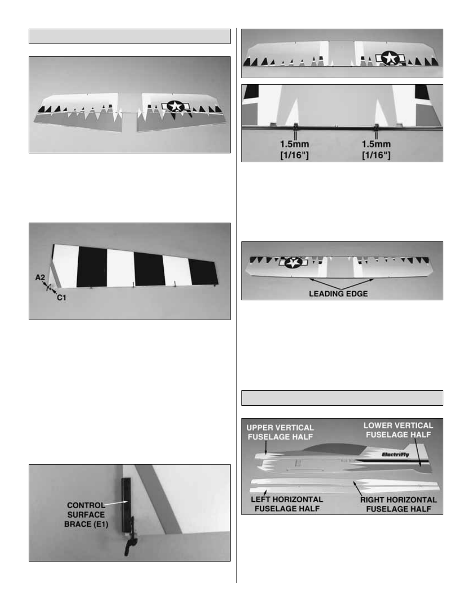
❏
1. Cut the wing and ailerons from the foam sheet.
❏ ❏
2. Insert offset Z-bend clevises (A2) into opposing
sides of two clip hinge control horns (C1). Following the
Expert Tip previously described, use the 3 x 863mm [1/8" x
34"] wing trailing edge tube as a guide to glue four hinges
and a control horn into each aileron. The control horns
should protrude from the bottom of the ailerons (black and
white side), and the offset Z-bend clevises should be on the
inboard sides of the horns. Remove the tube once the CA
has hardened.
❏ ❏
3. Glue a control surface brace (E1) onto the roots
of the ailerons.
❏
4. Slide four hinge retainer rings (C3) onto the wing
trailing edge tube. Position the rings so that they align with
the inner slots in the TE of the wing. Secure each retainer
with a drop of glue on the outside of the gap. Glue the
trailing edge tube to the TE of the wing. Be careful not to get
glue between the rings. Keep the 1.5mm [1/16"] spacing
between rings.
❏
5. Glue the 3 x 785mm [1/8" x 31"] wing leading edge
tube to the LE of the wing.
❏
1. Cut the upper and lower vertical fuselage halves
and the right and left horizontal fuselage halves free from
their foam sheets. If using the gearbox included with this kit,
or any other type of “stick-mount” gearbox, cut out all four
sections from the fuselage parts. If using a firewall-
mounted, brushless outrunner motor, cut out only the
section from the lower vertical fuselage.
Assemble the Fuselage
Assemble the Wing
9