Great Planes SpaceWalker ARF - GPMA1300 User Manual
Page 13
❏
5. If you installed a 2-stroke engine on your plane, install
the muffler and bend the throttle pushrod as needed to
avoid interference between the muffler.
❏
6. Switch your radio system on. Check that the throttle
opens and closes completely using the throttle stick and
trim on the transmitter. (See your radio instruction manual
for proper adjustment.) When satisfied with the operation of
the throttle, permanently attach the pushrod connector to
the servo arm with the plastic retainer and tighten the cap
screw onto the pushrod. Cut off the excess pushrod.
❏
7. Glue the throttle outer pushrod tube to the formers to
secure it in position.
❏
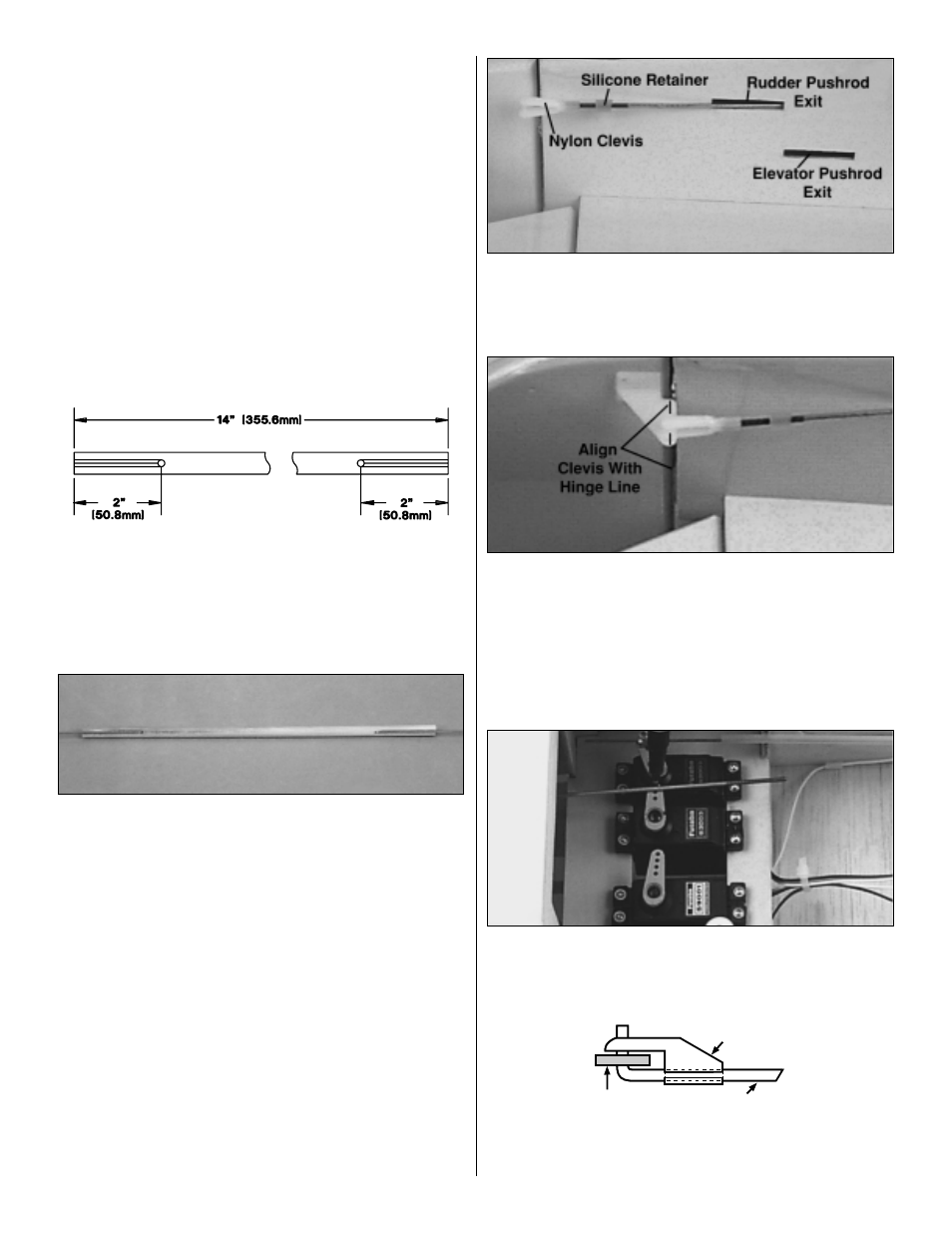
8. Cut both wood dowels to 14" [355.6mm] long.
❏
9. In one of the wood dowels, drill 5/64" [2mm] holes
through the dowel, 2" [50.8mm] from each end. On each
end of the dowel, use a hobby knife to cut a groove from
the hole to the end of the dowel, deep enough for a 2-56
threaded pushrod to fit in.
❏
10. From the threaded end of a 2-56 x36" pushrod, cut
an 11" [279.4mm] long piece. Cut a second non-threaded
11" [279.4mm] piece from the same 36" pushrod. Make a
90° bend 1/4" [6.4mm] from the non-threaded end of both
11" pushrods. Insert the “bent end” of the wire into the
holes in the wood dowel.
❏
11. Cut the 8" [203mm] shrink tubing into four 2" [50.8mm]
pieces. Slide a 2" [50.8mm] piece over each end of the
wood dowel and pushrod. Use a heat gun to shrink the
tubing tight around the dowel. Apply several drops of thin
CA to each end of the shrink tubing to secure it to the
dowel. This is now the rudder pushrod.
❏
12. Trim the covering from the two elevator pushrod
exits and the rudder pushrod exit at the aft end of the
fuselage. Apply a small amount of thin CA around the exits
to fuelproof them.
❏
13. Insert the rudder pushrod into the fuselage with the
threaded rod exiting out the rudder exit slot. Slide a silicone
clevis retainer over the rudder pushrod and screw a nylon
clevis 14 turns onto the rudder pushrod.
❏
14. Attach a control horn to the clevis. Align the clevis
holes in the control horn with the hinge line of the rudder.
Mark the control horn mounting holes.
❏
15. Drill a 3/32" [2.4mm] hole at both marks. Mount the
rudder control horn to the rudder with the backing plate and
two 2-56 x 5/8" machine screws. Slide the silicone retainer
over the clevis to secure it in place.
❏
16. With the servos centered and the rudder in the
neutral position, use a felt-tip pen to mark where the
pushrods cross the mounting holes in the servo arms.
❏
17. Make a 90° bend at the mark you made. Insert the
rudder pushrod in the rudder servo horn and secure it with
FasLink
2-56 (.074") Pushrod Wire
Servo Horn
13