Radio installation – Great Planes SpaceWalker ARF - GPMA1300 User Manual
Page 12
❏
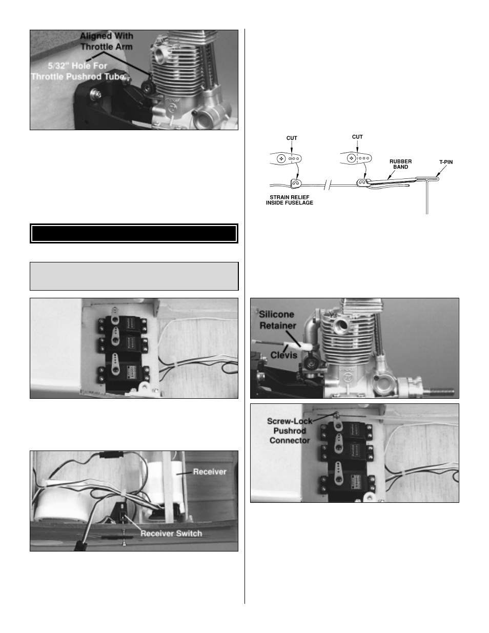
9. Drill a 5/32" [3.9mm] hole through the firewall and the
second former, in line with the throttle arm on the engine.
❏
10. Use coarse sandpaper to roughen the outside of the
throttle outer pushrod tube so the glue adheres well. Insert
the outer tube through the firewall and second former. Glue
the outer tube in place, leaving approximately 1/2"
[12.7mm] of the tube protruding from the front of the firewall.
❏
1. Install the servos in the servo tray, spacing them apart
as necessary so the servo arms do not interfere with each
other. Note: We recommend that a servo with at least 45
oz-in. [3.25 kg-cm] of torque be used on the elevators.
❏
2. Install the receiver switch on the left side of the
fuselage. We prefer a Great Planes Switch & Charge Jack
Mounting Set (GPMM1000). This allows the receiver battery
to be checked and charged at the flying field without
removing the wing. Wrap the receiver and receiver battery
in 1/4" [6.4mm] foam rubber to protect them from vibration.
Plug the servos, receiver switch and Y-harness into the
receiver. Secure the receiver in the fuselage with a couple
of scrap sticks glued to the sides of the fuselage.
Note: Do not permanently mount the receiver battery until
the step “Balance Your Model” on page 18 has been
completed.
❏
3. On our models we drilled a 1/16" [1.2mm] hole
through the top stringer of the turtledeck just behind the
cockpit. The receiver antenna is routed along the inside of
the fuselage and out this hole. The antenna is attached to
the fin with a T-pin, rubber band and a cut off servo arm.
❏
4. Temporarily install the brass Screw-Lock
™
Pushrod
Connector in the throttle servo arm. Slide a silicone
clevis retainer over the threaded end of a 2-56 x 36"
pushrod. Thread a nylon clevis 14 turns onto the
pushrod. Attach the clevis to the throttle arm on the
carburetor. Slide the throttle pushrod through the outer
pushrod tube and pushrod connector. Install a 4-40 x 1/8"
socket head cap screw in the pushrod connector.
Connect the clevis to the throttle arm and slide the silicone
clevis retainer into place.
Install the Throttle, Elevator and
Rudder Servos
RADIO INSTALLATION
12