Great Planes P-40 Warhawk GP/EP ARF - GPMA1472 User Manual
Page 22
22
❏
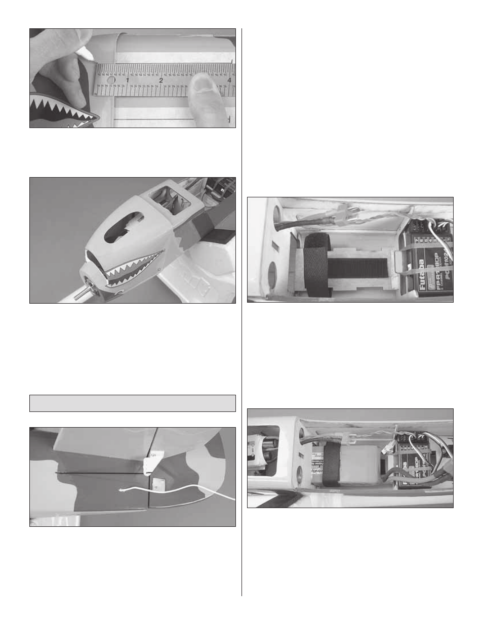
3. Measure forward 4" [102mm] from the aft marks on the
tape and mark the cowl for the mounting screw locations.
Drill 1/16" [1.6mm] holes through the cowl and through the
cowl mounting blocks at each mark.
❏
4. Remove the cowl and tape from the fuse. Cut the
necessary holes in the cowl appropriate for your power
system. The picture shows a cooling hole for the brushless
motor setup. Thread a 2mm x 8mm self-tapping screw into
each cowl hole in the fuse and remove it. Apply a couple
drops of thin CA into each hole to harden the wood. When
the CA has fully cured, install the cowl onto the fuse using
four 2mm x 8mm self-tapping screws.
Final Assembly
❏
1. The receiver antenna can be taped to the underside of
the fuse. For a cleaner look, we chose to route the antenna
down the inside of the fuse and out the side as shown. To do
this, we used a long scrap piece of pushrod tube we had in
the shop and inserted it through a small hole drilled beneath
the stab. Slide the tube through the hole toward the front of
the plane going through the cutouts in the formers. When
you reach the receiver with the tube, feed as much of the
antenna into the tube as possible, then pull the tube with the
antenna inside of it out through the hole.
❏
2. If you have not done so already, connect the elevator
and rudder servos to the receiver. If you have installed a glow
engine, an optional switch and charge jack (not included)
can be installed onto the side of the fuse wherever there is
free space. Make sure that it does not interfere with any of
the pushrods.
❏
3. If you have installed a brushless out-runner motor, mix
up a small batch of epoxy and brush a thin coating onto
the battery tray. This will improve the adhesion of the self-
adhesive hook and loop material. When the epoxy has cured,
apply the hook side of the included self-adhesive hook and
loop material to the battery tray (cut to length as needed).
❏
4. Install the loop side of the included self-adhesive hook
and loop material onto the battery pack. Some packs may be
able to be moved forward or aft to minimize additional weight
added to the plane for balancing purposes. Longer NiMH
packs may have little room to move along the battery tray for
balancing purposes. After the plane is completely assembled,
experiment with the position of the pack if possible when
balancing the plane and mark the optimum position of the
pack onto the battery tray for future reference.