Great Planes P-40 Warhawk GP/EP ARF - GPMA1472 User Manual
Page 15
15
reach the back of the tank but not touch. The clunk must be
able to move freely inside the tank when assembled. Adjust
the length of the fuel tubing accordingly. If you wish to use
the fi ll line to drain the tank, attach a length of fuel tubing and
an additional fuel clunk (not included) to the fi ll line inside the
tank. When satisfi ed, tighten the 3mm x 25mm screw in the
stopper to secure it in place (do not overtighten). Mark the
side of the tank that must face up when installed in the plane,
and we also suggest marking the tubes in the stopper.
❏
4. Insert the tank into the fuse with the correct side facing
up. The neck of the tank should pass through the hole in
the fi rewall.
❏
5. Cut a piece from the included 6mm x 6mm stick to fi t
between the stringers behind the fuel tank in order to secure
the tank in place as shown. When satisfi ed with the fi t, use
CA to glue the stick in place.
❏
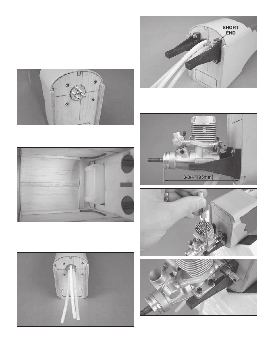
6. Attach a 6" [150mm] piece of fuel line to each of the
metal tubes in the fuel tank.
❏
7. Using four 3mm x 16mm machine screws, four 3mm
lock washers and four 3mm fl at washers, attach the engine
mount halves inverted to the fi rewall. The short end of the
engine mount halves should face up.
❏
8. Position the front of the engine drive washer 3-3/4" [95mm]
from the fi rewall. Mark the location of the engine mount holes
onto the engine mount halves using a Dead Center
™
Hole
Locator (GPMR8130). Remove the engine from the mount and