Great Planes Gee Bee ARF - GPMA1326 User Manual
Page 25
❏
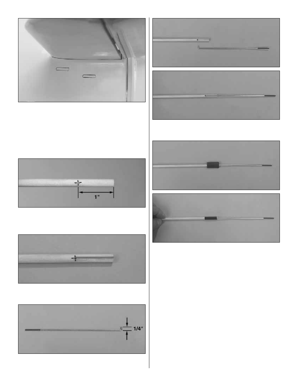
6. On the left side of the fuselage below the stab are
located two molded pushrod exit locations. Cut them out. On
the right side of the fuselage is located one molded pushrod
exit. Cut it out as well.
❏ ❏
7. Locate three .074 x 17-1/2" [444mm] wires threaded
on one end. From one wire cut a 6-1/2" [165mm] rod with the
threads at one end.
❏ ❏
8. Locate three 1/4" x 16" [6mm x 406mm] wood dowels.
On one dowel measure from one end 1" [25mm] and make a
mark. On the mark, drill a 5/64" [2mm] hole through the dowel.
❏ ❏
9. From the end of the dowel to the hole make a
groove the same width as the pushrod wire.
❏ ❏
10. On the non-threaded end of the 6-1/2" [165mm] wire
make a 90 degree bend 1/4" [6mm] from the end of the wire.
❏ ❏
11. Insert the wire into the hole in the dowel. Glue the
wire to the groove with a small amount of medium CA.
❏ ❏
12. Locate one of the 2-3/8" [60mm] long pieces of
heat shrink tubing. Cut it in half. Slide one piece over the
wire and the dowel. Then shrink the tubing tightly to the
dowel and wire. The tubing can be shrunk with either a
modeling heat gun or a match.
❏ ❏
13. From the leftover .074 x 17-1/2" [444mm] wire cut
a 7-1/2" [190mm] long, non-threaded wire. Make a 90 degree
bend 1/4" [6mm] from the end of the wire.
❏ ❏
14. On the opposite end of the dowel measure in 1"
[25mm] and make a mark. On the mark, drill a 5/64" [2mm]
hole through the dowel.
❏ ❏
15. From the end of the dowel to the hole make a groove.
❏ ❏
16. Insert the wire into the hole in the dowel. Glue the
wire to the groove with a small amount of medium CA.
❏ ❏
17. Slide the remaining half of the heat shrink tubing
over the wire and dowel. Shrink the tubing tightly to the
dowel and wire.
25
25