Great Planes AT-6 Texan ARF 40 MonoKote - GPMA1245 User Manual
Page 11
slide easily into the tube. Screw a nylon clevis on the
pushrod about 14 turns and add a silicone retainer to the
clevis. Trim the bottom hole from a control horn as shown in
the photo and attach the clevis to the outermost hole.
❏
13. Install the rudder nylon control horn in line with the
pushrod. Hold the horn in position and mark the location of
the mounting holes. Drill 3/32” (2.4mm) mounting holes
through the marks. Wick two to three drops of Thin CA into
the holes to harden the underlying balsa, then redrill the
holes. Attach the horns using 2-56 x 5/8” Machine Screws
and Nylon Nut Plates. Do not over-tighten the screws,
crushing the underlying balsa.
❏
14. Center the rudder and rudder servo and mark the
pushrod where it crosses the servo arm. Enlarge the servo
horn hole with a 5/64” (2mm) drill bit.
❏
15. Make a 90-degree bend in the pushrod on your
mark, then insert it through the enlarged hole in the servo
arm. Secure the wire in place with a nylon FasLink pushrod
keeper. Trim the excess wire just above the FasLink. Use
the photo showing the installation of the aileron linkage
for clarification.
❏
16. Insert the remaining two 2-56 x 36” threaded end
rods into the elevator tubes in the fuselage. Screw a nylon
clevis on each of the pushrods about 14 turns and add
silicone retainers to the clevises.
❏
17. Install the elevator nylon control horns in line with the
pushrods. Hold the horns in position and mark the location
of the mounting holes. Drill 3/32” (2.4mm) mounting holes
through the marks. Wick two to three drops of Thin CA into
the holes to harden the underlying balsa, then redrill the
holes. Attach the horns using four 2-56 x 5/8” machine
screws and nylon nut plates. Do not over-tighten the
screws, crushing the underlying balsa.
❏
18. Center one of the elevators and elevator servo and
mark the pushrod where it crosses the servo arm. Enlarge
the servo horn hole with a 5/64” (2mm) drill bit.
❏
19. Slide two of the 5/32” Wheel Collars onto the
pushrod wire that will attach to the elevator servo. Make a
90-degree bend in the pushrod on your mark, then insert it
through the enlarged hole in the servo arm. Secure the wire
in place with a nylon FasLink Pushrod Keeper. Trim the
excess wire just above the FasLink.
❏
20. While keeping both elevators centered, connect the
two elevator pushrods to each other with two 5/32” wheel
collars and two 6-32 x 1/4” Socket Head Cap Screws as
shown in the photo. Use threadlock on the screws to
prevent loosening.
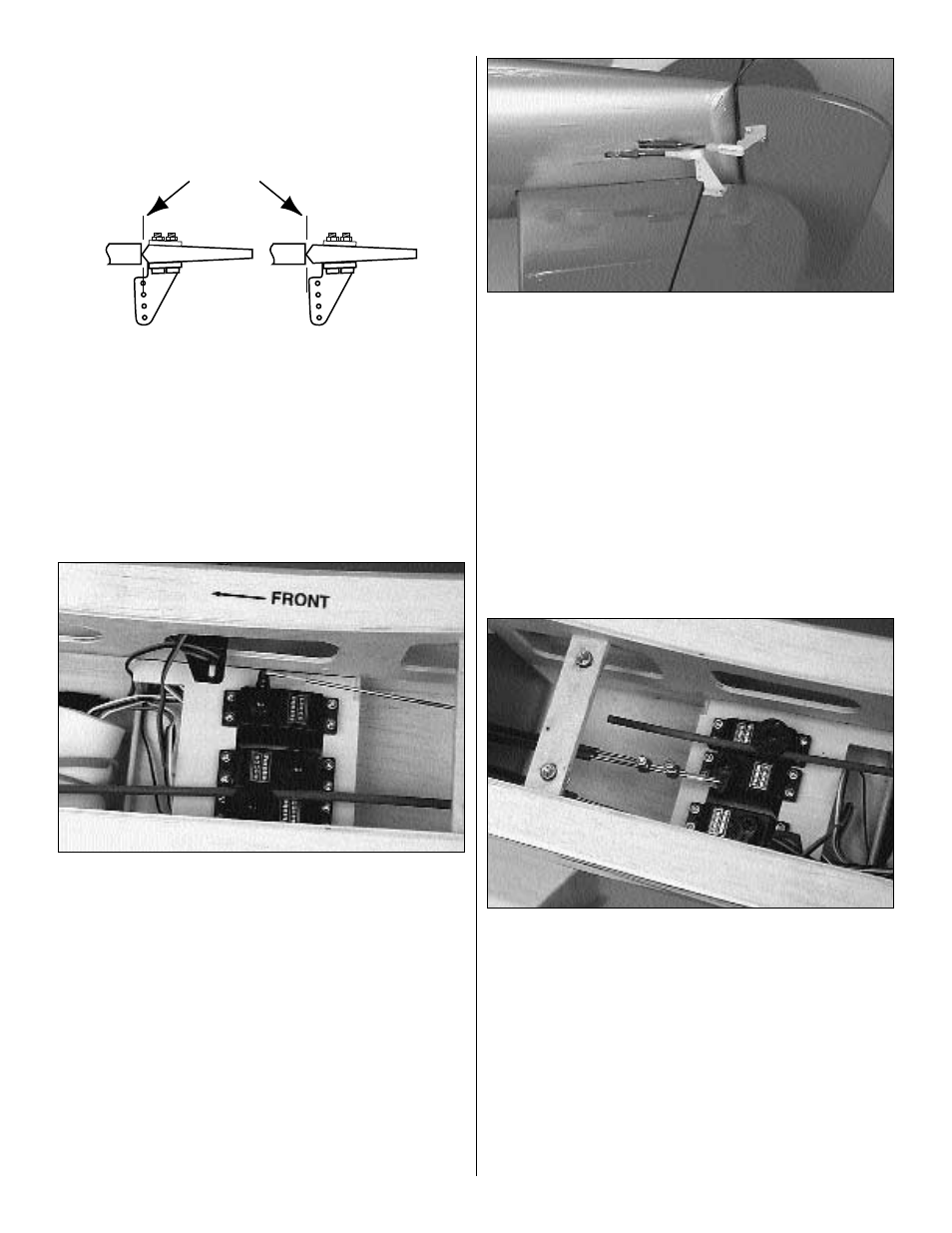
INCORRECT
CORRECT
HINGE LINE
11