Great Planes Piper J-3 Cub 40 Kit - GPMA0160 User Manual
Page 43
❏
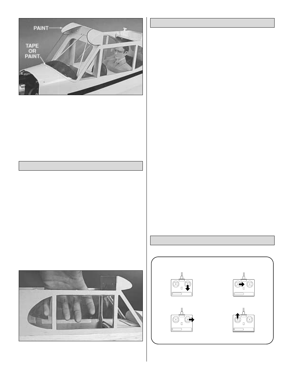
4. To hide the windshield glue joint, you may use 1/4" Cub
Yellow striping tape or paint a border around the windshield.
Also, paint the “Wing LE’s” (molded into the canopy) to
match the wing covering.
NOTE: Install the side windows after the model has
been covered.
❏
1. Using a hobby knife or scissors, cut the clear plastic
side windows from the sheet by cutting along the molded-
in trim lines. Notice that the front side windows are cut
separately from the sheet.
❏
2. Carefully sand the edges of each window panel with #400-
grit sandpaper to remove any irregularities caused by trimming,
but use care not to scratch the surface of the windows.
❏
3. Thoroughly clean the covering material around the
inside edges of the windows with alcohol, to remove all
traces of skin oils.
❏
4. Very carefully apply medium or thick CA (or another
glue, RC-56 etc.) to the window flanges. Position the window
in place and hold or tape it until the glue is cured.
NOTE: This section is VERY important and must not be
omitted! A model that is not properly balanced will be
unstable and possibly unflyable.
❏
1. Accurately mark the balance point on the bottom of the
wing on both sides of the fuselage. The balance point is
shown on the plan (CG), and is located approximately 4"
back from the leading edge. This is the balance point at which
your model should balance for your first flights. Later, you may
wish to shift the balance up to 3/8" forward or back to
change the flying characteristics. Moving the balance forward
results in a model that is more resistant to stalls and spins but
also may act sluggish and require more speed for takeoff and
landing. Moving the balance aft makes the model more agile
with a lighter and snappier “feel” and often improves snap roll
and knife-edge capabilities. In any case, do not balance
your model outside the recommended range.
❏
2. With the wing attached to the fuselage, all parts of the
model installed (ready to fly), and an empty fuel tank, block up
the tail until the bottom edges of the side windows are level.
❏
3. Lift the model at the CG marks. If the tail drops when
you lift, the model is “tail heavy” and you must add weight to
the nose to balance. If the nose drops, it is “nose heavy” and
you must add weight to the tail to balance. NOTE: Nose
weight may be easily installed by using an Aluminum
(GPMQ4630) or Brass (GPMQ4640) Spinner Nut, or by
screwing strips of lead onto the firewall under the engine.
Tail weight may be added by using “stick-on” lead weights
(GPMQ4485), and later, if the balance proves to be OK, you
can open the fuse bottom and glue these in permanently.
❏
1. Make sure the control surfaces move in the proper
direction as illustrated.
CARBURETOR WIDE OPEN
RUDDER MOVES RIGHT
LEFT AILERON MOVES DOWN
RIGHT AILERON MOVES UP
ELEVATOR MOVES UP
4-CHANNEL
TRANSMITTER
(STANDARD MODE 2)
4-CHANNEL RADIO SETUP
TRANSMITTER
4-CHANNEL
TRANSMITTER
4-CHANNEL
TRANSMITTER
4-CHANNEL
Final Hookups and Checks
Balance Your Model
Install Side Windows
43