Final fuselage assembly – Great Planes Piper J-3 Cub 40 Kit - GPMA0160 User Manual
Page 29
❏
6. While the engine is still mounted, determine where the
fuel lines and the throttle pushrod should pass through the
firewall and mark these locations. NOTE: With most tank
and engine combinations, the fuel lines can pass through
the center of the mount.
❏
7. Remove the engine from the engine mount and drill
1/4” holes for the fuel line holes. Center the mount on the
centerlines embossed on the firewall.
❏
8. Cut two pieces of 1/4" thick foam rubber (not
included) to match the outline of tank floors. Glue one piece
of the foam rubber to the top of the lower tank floor and the
other to the bottom of the top tank floor.
❏
9. We recommend a 10 oz. fuel tank for use with .40 - .50
size engines. The smaller tank size makes routing the
throttle pushrod easier. A 12 oz. tank can be used with
larger engines. Assemble your fuel tank and slide a section
of standard size fuel line, approximately 20" long, onto the
fuel nipple of the tank. With the tank inside the fuselage,
feed the fuel line through one of the firewall holes and mark
an “F” on the firewall to indicate that this is the fuel line.
Mark a “V” near the other hole to indicate it will be the vent
line. Feed the end of the line back through the other hole in
the firewall and attach it to the tank vent.
❏
10. Slide the fuel tank in between the two foam rubber
sheets and gently pull the fuel line forward at the same time.
CAUTION: Do not pull the fuel line hard enough to pull the
line off of the tank. Seal the line holes with silicone sealer.
❏
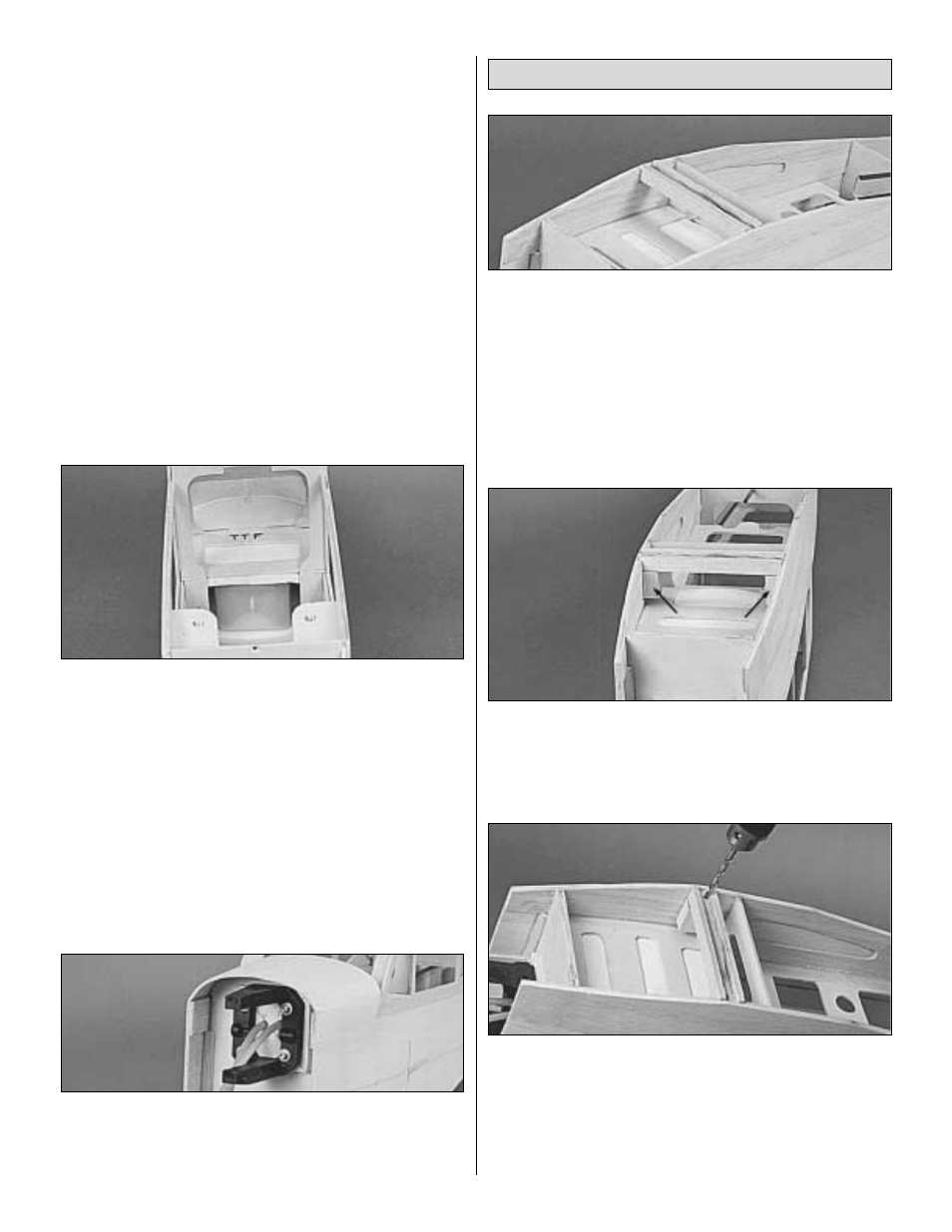
1. Test fit the 1/2" x 3/4" x 4-3/4" basswood Grooved LG
Block (CUB4F19) in the notches in the lower fuselage
doublers. Enlarge the notches if necessary to get it to fit.
Apply epoxy to the notches in the fuselage and the ends of
the LG block and press it into place. Notice that the LG block
is about 3/32" lower than the edge of the fuselage to match
up with the fuselage bottom sheeting.
❏
2. Epoxy the two 1/2" x 3/4" x 1" Basswood Short LG
blocks (CUB4F20) in place above the grooved LG block as
shown in the photo.
❏
3. Refer to the plans and the photo above to determine
where to drill the LG holes. One hole is near the aft edge of
the groove and the other hole is near the forward edge of
the groove. Both holes are centered approximately 3/8"
away from the fuselage side. Drill a 3/16" hole through the
grooved block and through the short LG block. Try to keep
the drill perpendicular to the grooved block during this step.
Final Fuselage Assembly
29