Build the elevators – Great Planes Piper J-3 Cub 40 Kit - GPMA0160 User Manual
Page 10
❏
2. Position the S1 and the two S4’s over their locations
on the plans. Check the fits of the joints and sand them if
necessary. Pin them in place.
❏
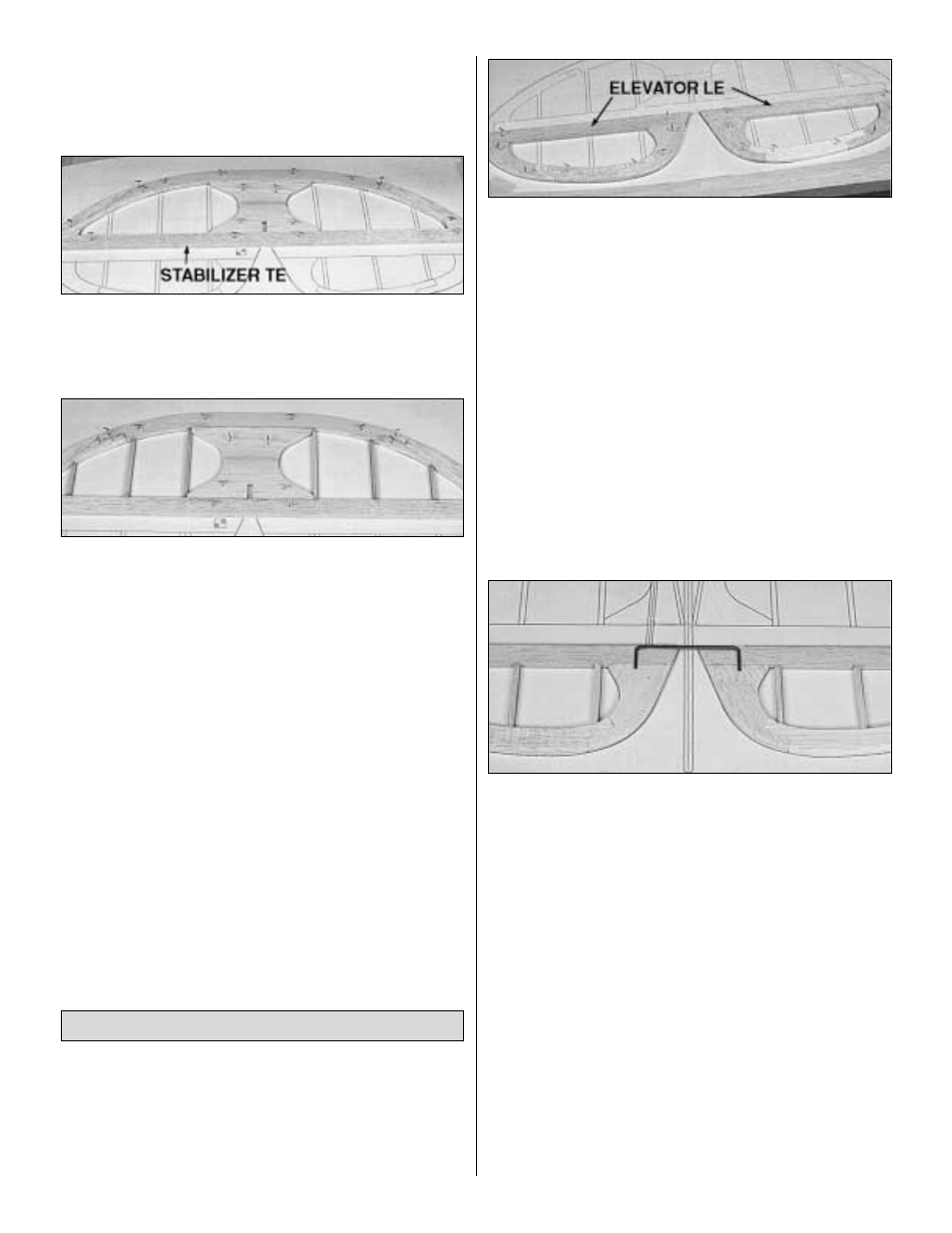
3. Cut the Stabilizer TE from the 1/4" X 3/4" X 24" balsa
strip (CUB4S03). Fit the TE between the S4’s and glue it in
place with thin CA.
❏
4. Cut the Ribs from the 3/16" x 1/4" x 24" balsa stick
(CUB4S04). Fit the Ribs in the stabilizer frame and glue
them in place with thin CA.
❏
5. Remove the stabilizer from the building board and
inspect all the glue joints. Glue all the tight fitting joints on
the bottom side of the stab with thin CA and add thick CA to
any open joints.
❏
6. Place the stabilizer on a flat work surface and lightly
sand both sides flat and smooth.
❏
7. Draw a centerline on the TE of the stabilizer. The
centerline will be used later to assist in positioning the hinges.
❏
8. Sand the LE only of the stabilizer to a nice rounded
shape as shown on the plans.
❏
1. Tape waxed paper over the Elevator drawing on the
fuse plan. Remove S5,S6,and S7 from the 1/4" die-cut balsa
sheet CUB4S02. Position the parts over the plans and
check the fit of the joints. Sand the parts as necessary to
ensure good fitting joints. Pin the parts in place over the
plans and glue them together with thin CA.
❏
2. Cut the Elevator LE from the 1/4" x 3/4" x 24" balsa
strip (CUB4S03) and pin it in place. Glue all the joints with
thin CA.
❏
3. Cut the elevator Ribs from the 3/16" x 1/4" x 24" balsa
stick (CUB4SO4). Fit the ribs in the elevator frame and glue
with thin CA.
❏
4. Remove the elevators from the building board and
inspect all the glue joints. Glue all the tight fitting joints with
thin CA and add thick CA to any open joints.
❏
5. Place the elevators on a flat work surface and lightly
sand both sides flat and smooth using a T-bar or other good
flat sanding block.
❏
6. Carefully draw a centerline all around the edges of
the elevators.
❏
7. Temporarily pin the elevators to the plan. Lay the 1/8"
wire elevator joiner (WBNT194) in place on the elevators
and mark its outline using a soft leaded pencil. NOTE: Mark
the elevator joiner wire outline very lightly so that it will not
be seen through the covering material.
❏
8. Accurately drill a 1/16" diameter pilot hole approximately
3/4" deep at each location. Then drill the final hole with a
9/64" drill bit to a depth of 7/8". (The hole is drilled slightly
oversize to allow for positioning, and to allow room to create
a hard epoxy “sleeve” around the wire. NOTE: The joiner wire
must be centered on the centerline of the stabilizer. The holes
must be drilled perpendicular to the LE and parallel to the top
and bottom surfaces of the elevators.
❏
9. Use the sharpened 1/8" diameter brass tube to cut
grooves in the leading edge of the elevators to accept the
joiner wire.
❏
10. Sand the LE to a “V”-shape and the entire TE to a
rounded shape. Check the plans for the proper cross-sections.
Build the Elevators
10