Great Planes ElectriCub Kit - GPMA0156 User Manual
Page 20
❏ ❏
4. Use a pen to mark the location on the longerons for
formers F-4, F-5 and F-6.
❏
5. Remove the fuselage side from the plans. Return to
step 1 and build the second fuselage side.
❏
6. Place the two fuse sides together and check that they
match up all the way around. If they are not identical, pin
them together and use a sanding bar to make them match.
❏
7. Lightly sand both sides of the fuselage sides to remove
any excess glue.
❏
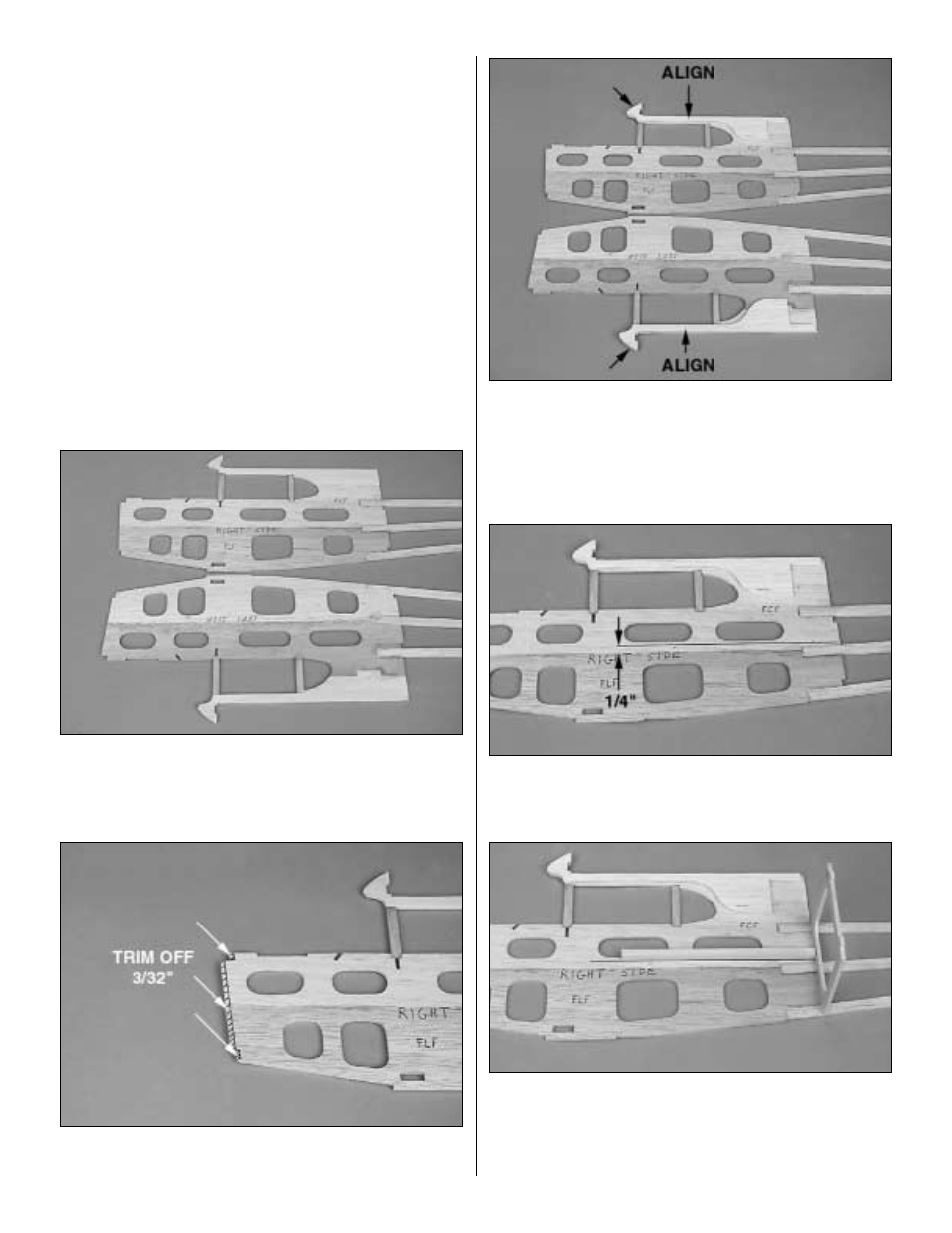
8. Lay the fuse sides next to each other so they mirror
each other. Mark one fuse side left side and one right side.
❏
9. To provide right thrust in the firewall, trim 3/32" off the
front of the right fuselage side.
❏
10. Align and glue the die-cut 1/8" balsa wing saddle
doublers to the inside of both fuse sides with the top and front
of the doubler aligned with the top and front of the fuse side.
❏
11. Cut the 1/4" x 1/4" x 12" basswood servo tray rail
in half.
❏ ❏
12. Draw a line on the inside of the fuse sides, 1/4"
above the joint between the forward lower fuse and the
forward center fuse.
❏ ❏
13. Temporarily install the die-cut 1/8" plywood former
F-3 in position on the fuse side. Glue the 1/4" x 1/4" servo
tray rail to the fuse side, aligning its bottom edge with the
line drawn in step 12 and former F-3. Do not glue the rail
to F-3.
20