Install the power system brushless motor – Great Planes U-Can-Do SF EP/GP .80 ARF - GPMA1272 User Manual
Page 13
13
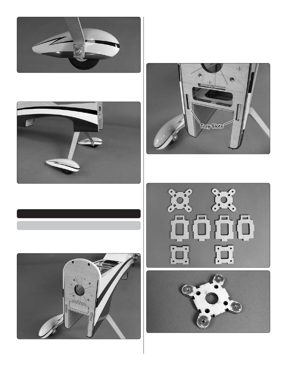
❏
3. Install the wheel pants onto the landing gear using four
2-56 x 1/2" [13mm] machine screws, four #2 lock washers,
four #2 fl at washers and thread locking compound. The angled
edge of the landing gear legs is the AFT edge.
❏
4. Attach the gear to the fuselage using two 6-32 x 3/4"
[19mm] machine screws, two #6 lock washers, two #6 fl at
washers and thread locking compound.
INSTALL THE POWER SYSTEM
Brushless Motor
This section only contains information relating to the installation
of a brushless power system. Skip this section if you plan to
install a glow engine.
❏
1. Drill four 11/64" [4.4mm] holes at the marks on the fi rewall
for the brushless motor mount. Note that there are two sets of
marks. Be sure to drill the holes as shown in the picture. It is
recommended to start with a small drill bit and work your way
up in size to 11/64" [4.4mm]. Doing this will improve accuracy
in the positioning of the holes and will reduce the amount of
tear-out from the backside of the holes. When completed,
install 6-32 blind nuts into the holes. Draw them fully into the
holes by threading a 6-32 x 5/8" [15.9mm] screw and #6 fl at
washer into each hole and tightening the screw.
❏
2. Use a sharp hobby knife to fi nish cutting out the ESC
tray slots and the cooling hole. Note that the fi rewall is made
up of two layers of plywood. The cooling hole is removed from
both layers. The three slots are removed from only one layer.
❏
3. Locate the pieces that make up the brushless motor
mount. Begin the assembly by gluing the two front pieces
together, making sure that the edges are fl ush with each other.