Assemble and install the main landing gear – Great Planes Revolver GP/EP ARF 70" - GPMA1019 User Manual
Page 12
12
❏
3. Install the rudder servo as shown using the hardware
included with the servo. With the rudder in the neutral
position and the rudder servo arm perpendicular to the
pushrod, mark where the pushrod crosses the outer hole of
the servo arm. As you did with the elevator pushrod, make a
90 degree bend at the mark and cut off the excess pushrod
1/4" [6.4mm] beyond the bend. Drill a 5/64" [2mm] hole in
the servo arm and then secure the pushrod to the servo arm
with a nylon FasLink. Make any adjustments necessary to
the nylon clevis so that the rudder is properly centered and
slide the silicone clevis retainer to the end of the clevis.
Assemble and Install
the Main Landing Gear
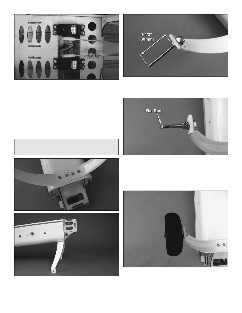
❏
1. Attach the landing gear legs to the fuselage using four
8-32 x 3/4" [19.1mm] SHCS, four #8 fl at washers, four #8
lock washers, and thread locking compound. When installed
properly the landing gear sweeps back.
❏ ❏
2. Cut the axles to a length of 1-1/2" [38mm]. Secure
the axles to the landing gear legs using the 5/16"-24 nylon
lock nuts.
❏ ❏
3. Slide a 3/16" [4.8mm] wheel collar onto each axle
followed by a 3-1/4" [83mm] wheel and then another 3/16"
[4.8mm] wheel collar. Mark the location of the threaded
holes in the wheel collars onto the axles. Use a fi le or
rotary tool such as a Dremel to grind fl at spots at the
marks on the axles.
❏ ❏
4. Reinstall the wheel collars and wheels onto the
axles. Thread a 6-32 set screw into each wheel collar and
tighten the set screws against the fl at spots on the axles. Be
sure that the wheel rotates freely on the axle. Oil the axles
if necessary.