Motor, esc, & radio installation – Great Planes Mister Mulligan EP ARF - GPMA1485 User Manual
Page 18
18
❏
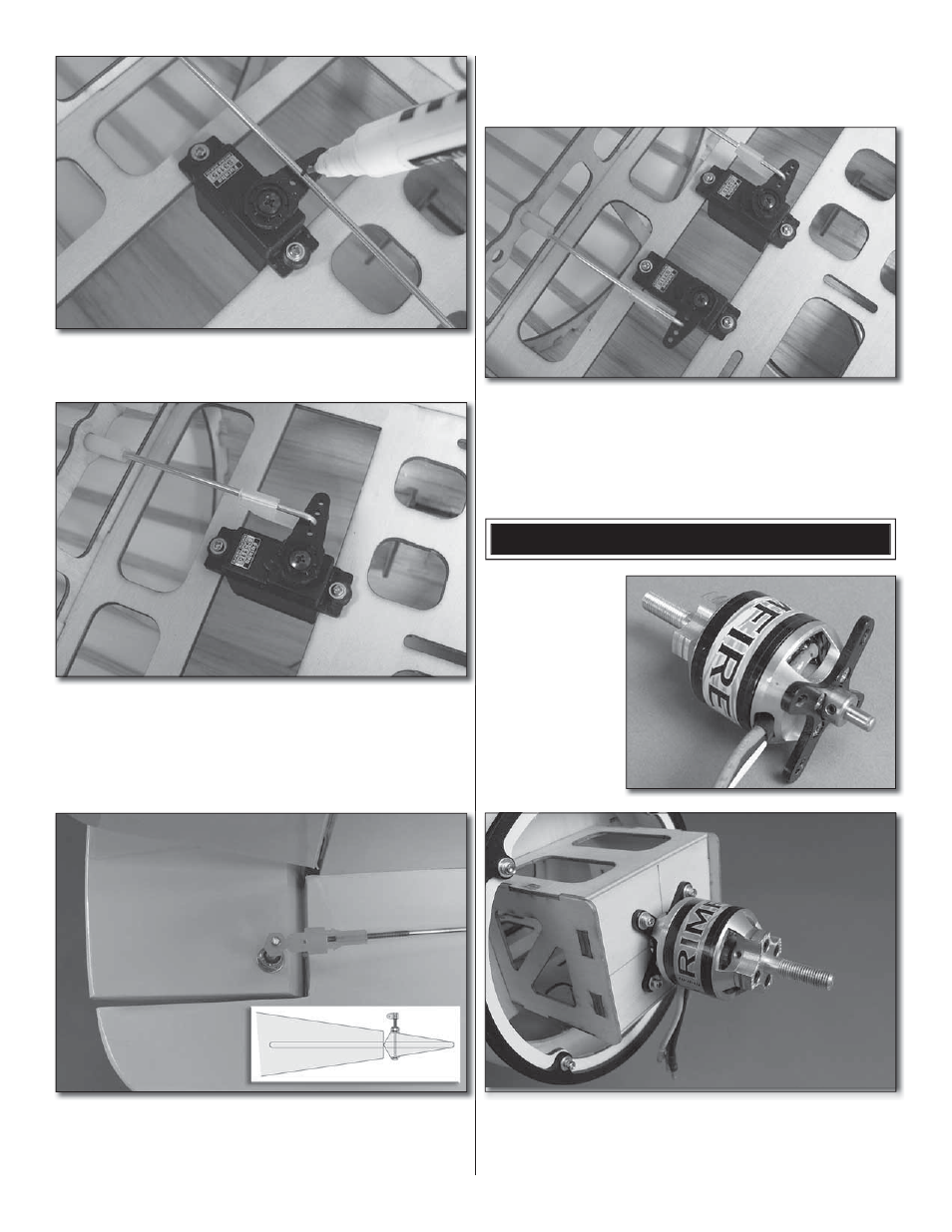
7. Drill the servo arm at the second hole outboard using
a 5/64 [2mm] drill. Hold the elevators at zero throw and mark
where to bend the elevator pushrod.
❏
8. Bend the pushrod 90° and trim the excess pushrod so
that at least 1/4" [6.4mm] of pushrod remains. Connect the
pushrod to the second hole of the servo arm. Use a nylon
Faslink to secure the pushrod.
❏
9. Fit the other pushrod to the rudder guide tube on the
right side of the fuselage.
❏
10. Assemble the rudder horn as shown in the sketch. Fit
a #6 flat washer under the head of the 6-32 x 2" machine
screw and fit the screw to the rudder so that the head of the
screw is on the left side of the rudder. Use a #6 flat washer
and a #6 lock nut to secure the screw. Now screw a nylon
torque rod horn onto the threaded end of the screw so that it
is flush with the end. Connect the clevis.
❏
11. Prepare a servo. Install the rudder servo the same
way you installed the elevator servo. Bend the pushrod 90°
and trim the excess pushrod so that at least 1/4" [6.4mm] of
pushrod remains. Connect the pushrod to the second hole of
the servo arm using a nylon Faslink to secure it.
MOTOR, ESC, & RADIO INSTALLATION
❏
1. Install the
standard X-mount
to the back of the
Rimfire .32 motor
using the screws
supplied with the
motor. Apply a drop
of threadlocker to
the threads before
installing the screws.
❏
2. Orient the motor wires as shown and attach the motor
to the firewall with four 4-40 x 1/2" socket head cap screws,
four #4 lock washers and four #4 flat washers. Use thread
locking compound on the screw threads for added security.