Great Planes Cessna 182 Skylane 40 ARF - GPMA1228 User Manual
Page 14
❏
14. Cut a slot in the left side of the fuselage for the rudder
pushrod tube to exit the fuselage.
❏
15. Use a 3/16" [5mm] drill bit or a sharpened 3/16" [5mm]
brass tube to chamfer the holes for easier installation of the
pushrod tube.
❏
16. Locate a 36" [914mm] outer pushrod guide tube and
scuff the outside with coarse grit sandpaper. Route the tube
through the fuselage and into the radio compartment. The tube
must protrude at least 1/2" [13mm] from the fuse side exits.
Glue the tube to the fuselage using medium CA.
❏
17. Insert one of the 2-56 x 36" threaded end rods into the
rudder tube in the fuselage. The pushrod should slide easily
into the tube. Thread a nylon clevis on the pushrod 14-turns
and add a silicone retainer to the clevis.
❏
18. Install the rudder nylon control horn in line with the
pushrod. Hold the horn in position and mark the location of
the mounting holes. Drill 3/32" [2.5mm] mounting holes
through the marks. Wick two to three drops of thin CA into
the holes to harden the underlying balsa, then re-drill the
holes. Attach the horn using two 2-56 x 5/8" machine screws
and a nylon nut plate. Do not overtighten the screws,
crushing the underlying balsa.
❏
19. Center the rudder and rudder servo and mark the
pushrod where it crosses the servo arm. Enlarge the servo
horn hole with a 5/64" [2mm] drill bit.
❏
20. Make a 90º bend in the pushrod on your mark, then
insert it through the enlarged hole in the servo arm. Secure
the wire in place with a nylon FasLink pushrod keeper. Trim
the excess wire protruding from the FasLink.
❏
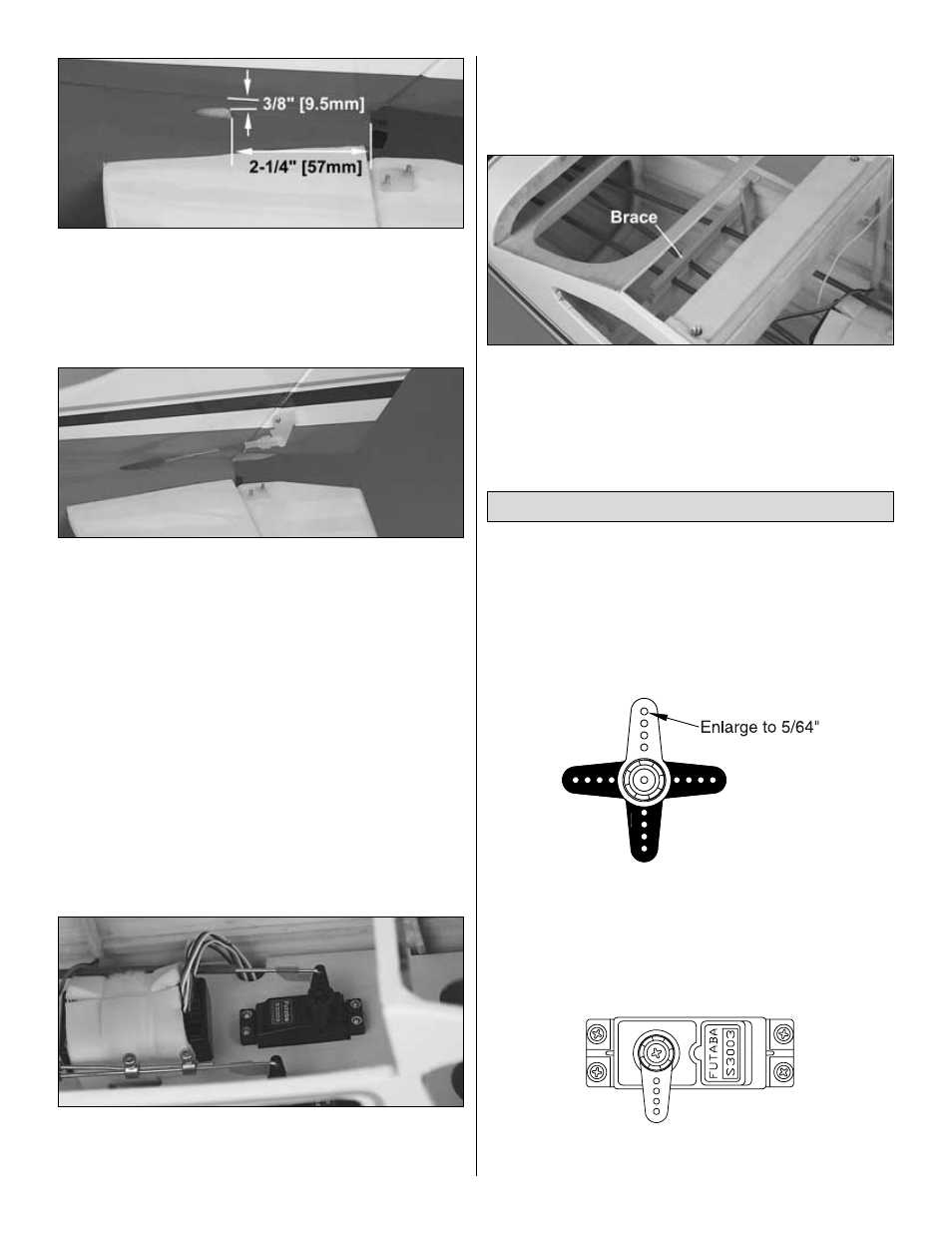
21. Once the rudder and elevator pushrods have been
installed, a brace must be constructed to support the
pushrods near the servo. Use balsa or mixing sticks to make
the brace (not included). Position the brace so the pushrods
will not bind when the controls are operated. Secure the
brace using medium CA.
Prepare two “cross” style servo horns as follows but don’t
install them on the servos until instructed to do so.
Note: The size and shape of servo horns varies from
manufacturer to manufacturer. The sketches and photos
show a typical radio installation with standard servo horns.
All standard servo horns should fit in the Cessna 182.
❏
A. Cut off three arms from two servo horns included with
your radio control set to make them into “one arm” servo
horns. Use your Bar Sander to remove the remaining jagged
edges left from the cut-off arms.
❏
B. Enlarge the holes in the horns with a 5/64" [2mm] drill.
❏
C. Connect the aileron servos to the receiver. Turn on your
transmitter and receiver, then position the aileron trim tabs
Aileron Servo Installation
14