Adjustments, Shave plate and skid shoes, Skid shoes – Cub Cadet 945 SWE User Manual
Page 16: Shave plate, Shift cable, Chute bracket adjustment, Chute control
Shave Plate and Skid Shoes
The shave plate and skid shoes on the bottom of the snow
thrower are subject to wear. They should be checked periodically
and replaced when necessary.
Skid Shoes
NOTE: The skid shoes on this machine have two wear edges.
When one side wears out, they can be rotated 180° to use the
other edge. Refer to the Assembly section for instructions on
adjusting the skid shoes.
1.
Remove the six carriage bolts, flat washers and hex nuts that
secure the two skid shoes to the sides of the auger housing.
Refer to Fig. 6-3.
2.
Position the new skid shoes and secure with the carriage
bolts, flat washers and hex nuts. Make certain the skid
shoes are adjusted to be level.
Shave Plate
1.
Remove the hex nuts and carriage bolts that secure the
shave plate to the bottom of the housing. See Fig. 6-3.
2.
Remove the rear most hex nut and carriage bolt securing
the back of each skid shoe to the sides of the housing.
Loosen the remaining hex nuts securing the skid shoes.
3.
Slide the shave plate out of the off-set slot at the bottom
of the housing, and from between the skid shoes and side
panels of the housing.
4.
With the mounting holes toward the back of the unit, slide
the new shave plate into position and secure with the
fasteners previously removed and loosened.
Adjustments
Shift Cable
If the full range of speeds (forward and reverse) cannot be
achieved, refer to the Figure 6-4 and adjust the shift cable as
follows:
1.
Place the shift lever in the fastest forward speed position.
2.
Loosen the hex nut on the shift cable index bracket. See
Fig. 6-4.
3.
Pivot the bracket downward to take up slack in the cable.
4.
Retighten the hex nut.
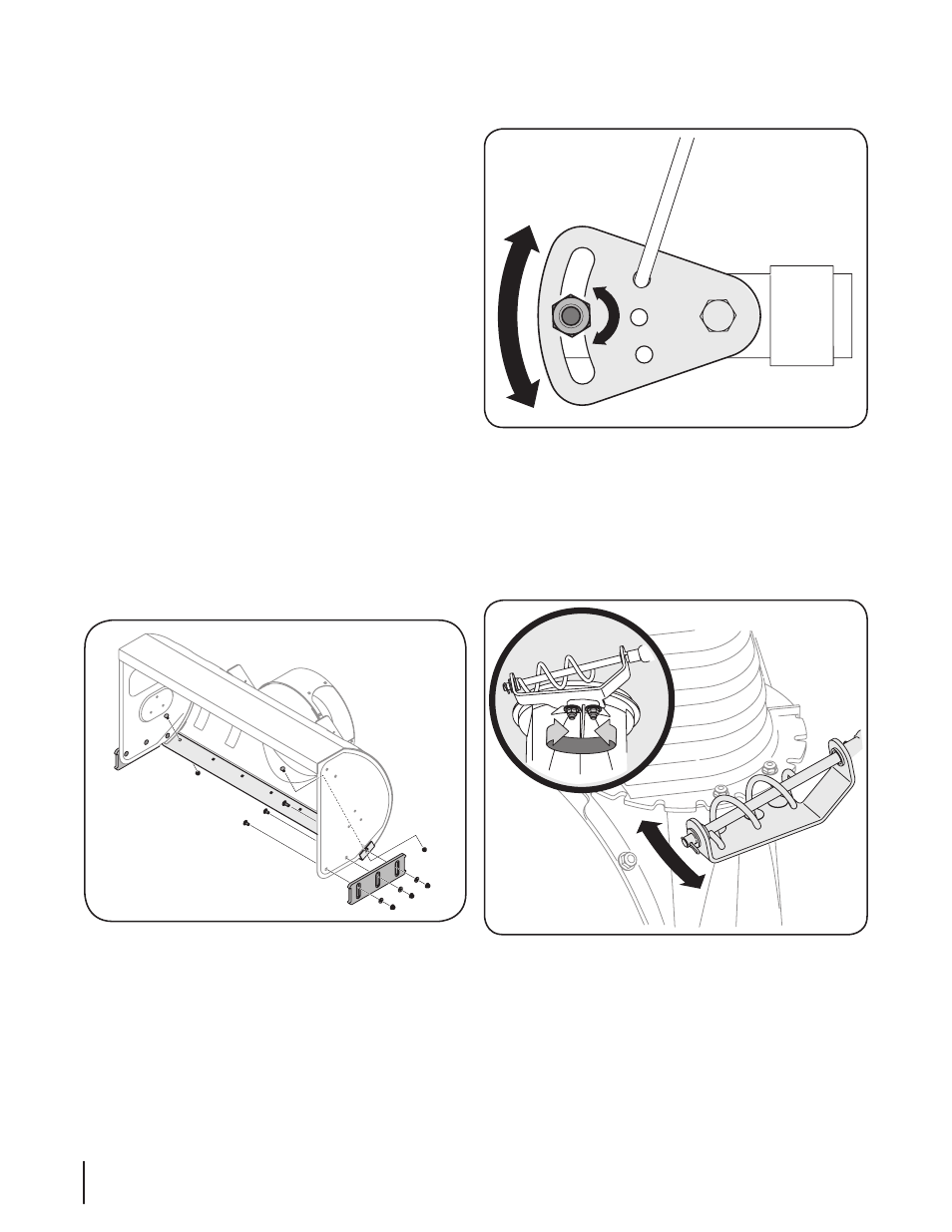
Chute Bracket Adjustment
If the spiral at the bottom of the chute directional control is not
fully engaging with the chute assembly, the chute bracket can be
adjusted. To do so:
1.
Loosen the two nuts which secure the chute bracket and
reposition it slightly. See Figure 6-5.
2.
Retighten the nuts.
Chute Control
The distance snow is thrown can be adjusted by adjusting the
angle of the chute assembly. Refer to the Operation section for
instructions.
The remote chute control cables have been pre-adjusted at
the factory. Move the remote chute lever on the control panel
forward to pivot the upper chute down; move the lever rearward
to pivot the upper chute up.
Figure 6-3
Figure 6-3
Figure 6-5
16
S
ection
6— M
aintenance
& a
djuStMentS