Electrical wiring – GME GR968 User Manual
Page 8
9
4. Slide the GR968 back into the bracket slots and adjust
for the correct position before tightening the
gimbal knobs.
5. Complete the antenna lead and electrical wiring as
described later.
Flush Mounting
The GR968 can be neatly flush mounted into a panel or
bulkhead so that just the controls and the protective cover
are visible. There are two flush mounting options available.
The best option for you will depend on your particular
situation.
• If the space behind the bulkhead or panel you have
selected has a suitable support shelf and the area is fully
accessible, you can use the supplied escutcheon panel as
described later.
• I f the space behind the bulkhead or panel is largely
inaccessible or there is no additional support shelf, we
recommend you use the optional MK900 flush mounting
kit (available as an accessory). This kit
is more robust, is fully self-supporting
and allows the
GR968 to be
installed from
the front.
Installation using the supplied Escutcheon Panel.
1. Select a suitable location on a panel or bulkhead.
Examine behind the bulkhead to determine the best
method of support for the CD player.
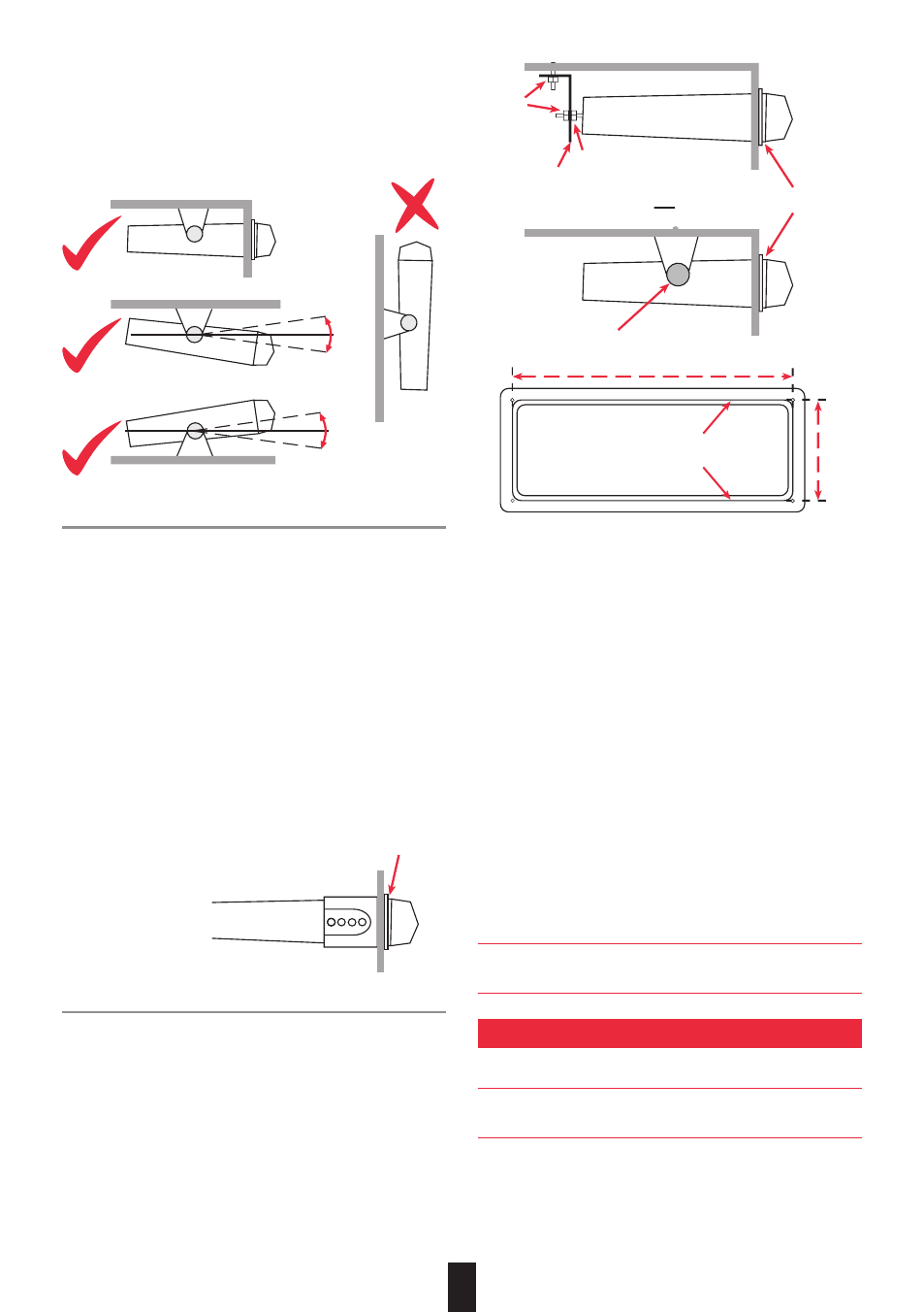
2. Place the escutcheon on the panel or bulkhead in the
required position and mark around the outside edge of
the escutcheon slot wall (see following diagram).
3. Remove the escutcheon and measure the marks. They
should measure approximately 200 mm wide and
70 mm high. If not, check the diagram above to ensure
that you have measured the correct edge.
4. If your measurements are correct, carefully cut the slot
around the marked lines, ensuring that you maintain
the curves in each corner. Mark and drill the four 2 mm
holes in the bulkhead to accept the locating pins at each
corner of the escutcheon.
5. Trial fit the escutcheon to ensure it fits securely against
the panel. If all is well, place a small dab of glue on
each locating pin and press the escutcheon into place.
Temporarily hold with tape if necessary.
6. With the escutcheon firmly glued in place, slide the
GR968 through the slot from the front and push it all the
way in, while leaving a clearance for the front cover to
hang in the open position. Open the cover if necessary
to ensure the correct clearance.
7. Holding everything in position mark the location of the
internal support bracket(s). Drill the required holes and
fit the bracket(s) as required to hold the GR968 firmly
in place.
Note: If using the perforated metal support strip, mount it
to the rear of the GR968 as shown in the diagram.
ELECTRICAL WIRING
DC Connections
Caution: The GR968 is designed for vessels with a 12 Volt
negative ground electrical system only!
Referring to the wiring diagram on page 9:
1. Connect the Yellow wire labelled ‘MEMORY 12 V+’
directly to the positive terminal of the vessel’s battery, or
to a point that has +12 Volts available at all times.
FLUSH MOUNT
30˚
30˚
OVERHEAD MOUNT
ON DASH MOUNT
30˚
30˚
ESCUTCHEON
NUT
NUT
ESCUTCHEON
PERFORATED STRIP
OR
MOUNTING BRACKET
FLUSH MOUNT
30˚
30˚
OVERHEAD MOUNT
ON DASH MOUNT
30˚
30˚
ESCUTCHEON
NUT
NUT
ESCUTCHEON
PERFORATED STRIP
OR
MOUNTING BRACKET
FLUSH MOUNT
30˚
30˚
OVERHEAD MOUNT
ON DASH MOUNT
30˚
30˚
ESCUTCHEON
NUT
NUT
ESCUTCHEON
PERFORATED STRIP
OR
MOUNTING BRACKET
IMPORTANT DRAW
AROUND THIS EDGE
70 m
m
200 mm
8