Control, Volume, Plastic tab – GME TX4500S User Manual
Page 26
PA G E 2 6
I N S T R U C T I O N M A N UA L
T X 4 5 0 0 S
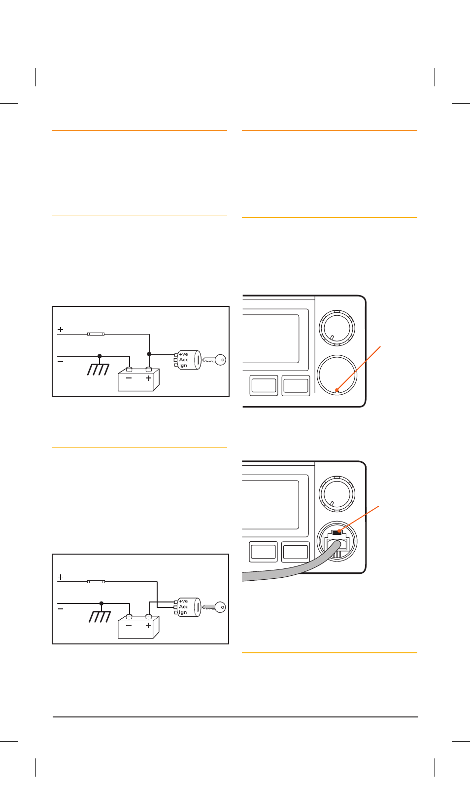
DC POWER CONNECTION
The TX4500S is designed for 13.8 V DC negative
earth installations only (i.e. where the negative side
of the battery is connected to the frame or chassis of
the vehicle). There are two recommended methods of
installation. Please refer to the following diagrams.
Radio Remains On when the Ignition Switch
is Off
Connect the radio’s negative (Black) lead to the
vehicle’s chassis or if preferred directly to the
battery’s negative terminal.
Connect the radio’s positive (Red) lead, via the
2 Amp fuse, to the battery’s positive terminal or
to a point in the fuse box that has +13.8 volts
continuously available.
Radio remains ON when ignition switch is OFF
RED
Fuse
Fuse
BLACK
Chassis
Car battery
Ingnition Switch
Radio turns ON and OFF with ignition switch
RED
BLACK
Chassis
Car battery
Ingnition Switch
To Radio
To Radio
The radio can now be switched On or Off at any
time using the switch on the
Volume
control.
Radio Turns On and Off with the Ignition Switch
Connect the radio’s negative (Black) lead to the
vehicle’s chassis or if preferred directly to the
battery’s negative terminal.
Connect the radio’s positive (Red) lead, via the 2
amp fuse, to the accessory point in the fuse box.
This point should supply +13.8 volts ONLY when
the ignition is switched ON or in the ACCESSORY
position.
Radio remains ON when ignition switch is OFF
RED
Fuse
Fuse
BLACK
Chassis
Car battery
Ingnition Switch
Radio turns ON and OFF with ignition switch
RED
BLACK
Chassis
Car battery
Ingnition Switch
To Radio
To Radio
The radio should now switch ON and OFF
automatically with the vehicle’s ignition switch.
MICROPHONE
The TX4500S is fitted with two microphone sockets
– one on the front panel and one on the rear. The
6 pin microphone connector can be plugged into
either socket. In fact, if the situation requires it, two
microphones can be connected simultaneously. The
first microphone keyed takes priority.
Front
The front microphone socket is fitted with a hard
protective cover. The cover is a press fit. To remove
the cover, insert a paper clip or similar into the small
slot in the edge of the cover and lift the cover away
from the panel. Retain the cover in case you require
it later on.
SILEN T
QUIE T
DUP
ALPH A
VOLUME
Lift panel
here
Position the microphone plug so the plastic tab faces
upwards then press the plug into the socket until
it ‘clicks’.
SILEN T
QUIE T
DUP
ALPH A
VOLUME
Plastic tab
Gently press the rubber strain relief grommet
into the hole surrounding the socket so that the
slot around the grommet fits neatly inside the lip
inside the hole.
Rear
If using the rear microphone connection you
should obtain the optional LEM6P rear microphone
extension lead. Mount the socket on a convenient
location and feed the plug through the dashboard to
the DIN cavity.
46885-4_TX4500S_IM.indd 26
4/06/14 3:08 PM