Degrees, Inches, Millimeters – Flyzone FLZA3004 User Manual
Page 15
15
Aileron Throw
Flap Throw
Elevator Throw
Rudder Throw
❏
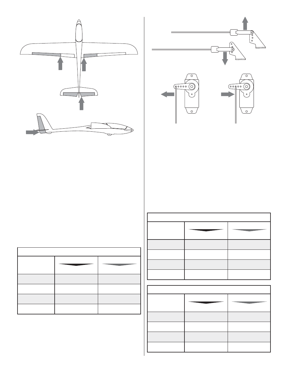
3. Note that the throw measurements for the elevator, rudder
and fl aps (if used) are taken at the widest part (front to back)
of each surface, but the aileron throw is measured at the split
between the fl aps and elevator (whether or not you have set
up the optional fl aps and cut the two apart).
Recommended Control Surface Throws
DEGREES
ELEVATOR
LOW RATE
HIGH RATE
12 º
Up
12 º
Down
18 º
Up
18 º
Down
AILERONS
11 º
11 º
19 º
19 º
RUDDER (R&L)
14 º
14 º
19 º
19 º
FLAP
22 º
Less Control Throw
More Control Throw
More
Control
Throw
Less
Control
Throw
❏
4. If necessary, use the programming in your transmitter or
mount the pushrods in different holes in the control horns or in
the servo arms to increase or decrease the elevator throw as
required. Moving the pushrods inward in the servo or outward
on the control surface horn decreases control throw. Moving
the pushrods outward on the servo or inward on the control
surface increases the throw.
❏
5. Measure and adjust if necessary the control throws for
the rudder, ailerons and fl aps the same way.
Recommended Control Surface Throws
INCHES
ELEVATOR
LOW RATE
HIGH RATE
1/2"
Up
1/2"
Down
3/4"
Up
3/4"
Down
AILERONS
3/8"
3/8"
5/8"
5/8"
RUDDER (R&L)
3/4"
3/4"
1"
1"
FLAP
7/8"
Recommended Control Surface Throws
MILLIMETERS
ELEVATOR
LOW RATE
HIGH RATE
13 mm
Up
13 mm
Down
19 mm
Up
19 mm
Down
AILERONS
10 mm
10 mm
16 mm
16 mm
RUDDER (R&L)
19mm
19mm
25 mm
25 mm
FLAP
22 mm