Components – FloAire DIRECT FIRED MODULE User Manual
Page 20
20
Components
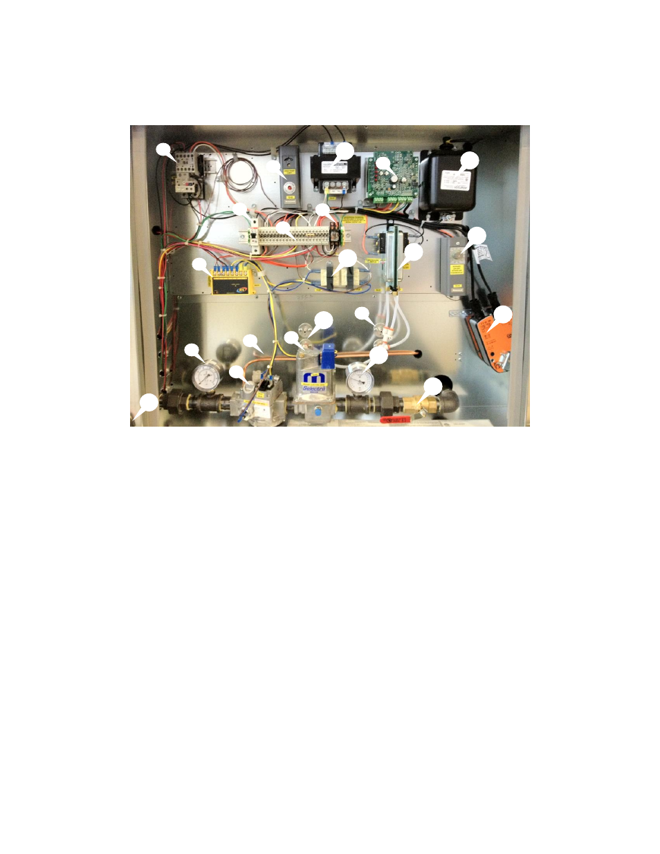
The following image and list outlines the typical direct fired heater components and their functions.
1. Gas Inlet
– Main gas supply connection
2. Motor Starter
– Contactor with overload protection to start and protect motor.
3. Cooling Interlock Relay (Optional)
– Energizes power to cooling circuit on call for cooling.
4. Inlet Gas Pressure Gauge
– Inlet gas pressure should be read from here.
5. Combination Gas Valve - A combination of redundant solenoid valves, pilot valve and gas
regulator built into one unit.
6. Pilot Tubing
– Pilot tube connection to combination gas valve.
7. Manual Reset High Temperature Limit
– Safety device that prevents the heater from
overheating.
8. Modulating Amplifier - Regulates temperature by a modulating gas valve
9. Power Transformer
– Installed when motor voltage > 120V. Used to provide 120V service to
controls.
10. Circuit Breaker
– Protects electrical components from high current spikes.
11. Terminal Strip
– Central location to terminate control wiring. Should be used for troubleshooting.
12. Control Transformer
– 120V primary; 24V secondary control transformer.
13. Low Pressure Airflow Probe
– Measures profile pressure downstream of burner.
14. High Pressure Airflow Probe
– Measures profile pressure upstream of burner.
15. Modulating Gas Valve
– Modulates gas flow to burner to provide proper air temperature.
16. Manifold Gas Pressure Gauge
– Manifold gas pressure should be read from here.
17. Flame Safety Control
– Initiates and monitors flame.
18. Airflow Switch
– A safety device insuring proper air flow during burner operation.
19. Ignition Transformer
– Produces high voltage spark to ignite flame.
20. Intake Air Thermostat
– De-energize heating circuit when intake air exceeds set-point.
21. Damper Actuator
– Motor containing end switch that opens intake damper.
22. Manual Gas Shut-Off Valve Allows gas flow to burner to be shut off to leak test gas train
1
7
21
20
16
22
9
19
13
15
17
6
5
4
2
8
10
11
14
18
3
12