Flintec 52-18SS User Manual
Page 11
11
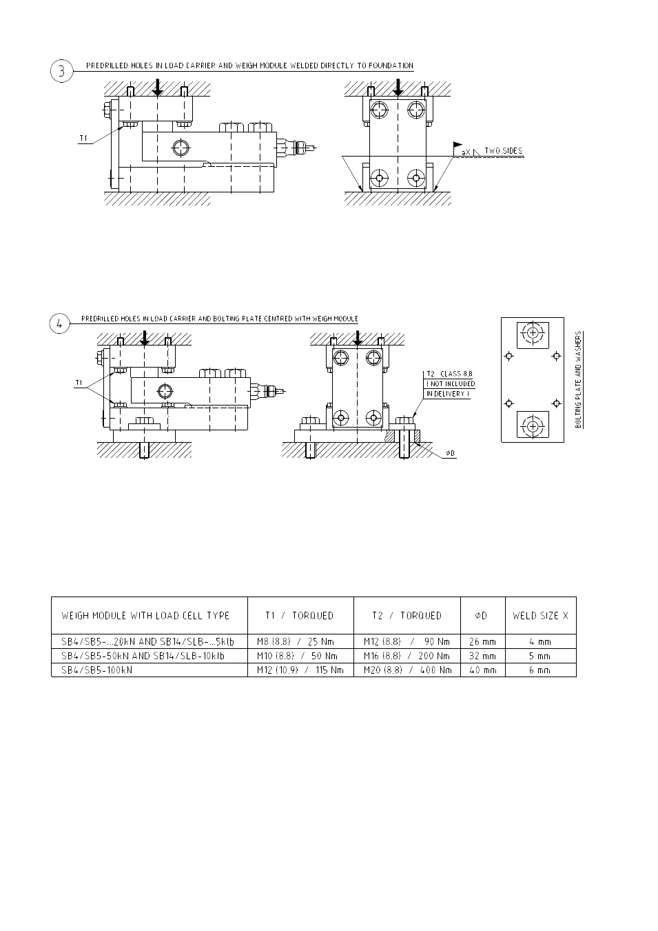
-Figure 3 is similar to 2b, but in this case, the base plate of the weigh module is welded directly to the foundation
plate without any welding plate in between.
-Figure 4 shows a case with pre-drilled mounting holes both in load carrier and in foundation and where the
weigh module has been fitted with a bolting plate on bottom side. The bolting plate has extra large clearance
holes for the mounting bolts, which can compensate for a considerable misplacement of the mounting holes.
With bolting plates both on top and bottom the compensation range is doubled.
-The above table shows weld sizes and torques required to withstand the max specified side forces of a weigh
module. For applications with no, or very small, side forces, these values of course can be selected differently.