Din rail universal dimmer crestron din-1dimu4 – Crestron electronic DIN Rail Universal Dimmer DIN-1DIMU4 User Manual
Page 14
DIN Rail Universal Dimmer
Crestron DIN-1DIMU4
Connectors, Controls & Indicators (Continued)
# CONNECTORS
1
,
CONTROLS &
INDICATORS
DESCRIPTION
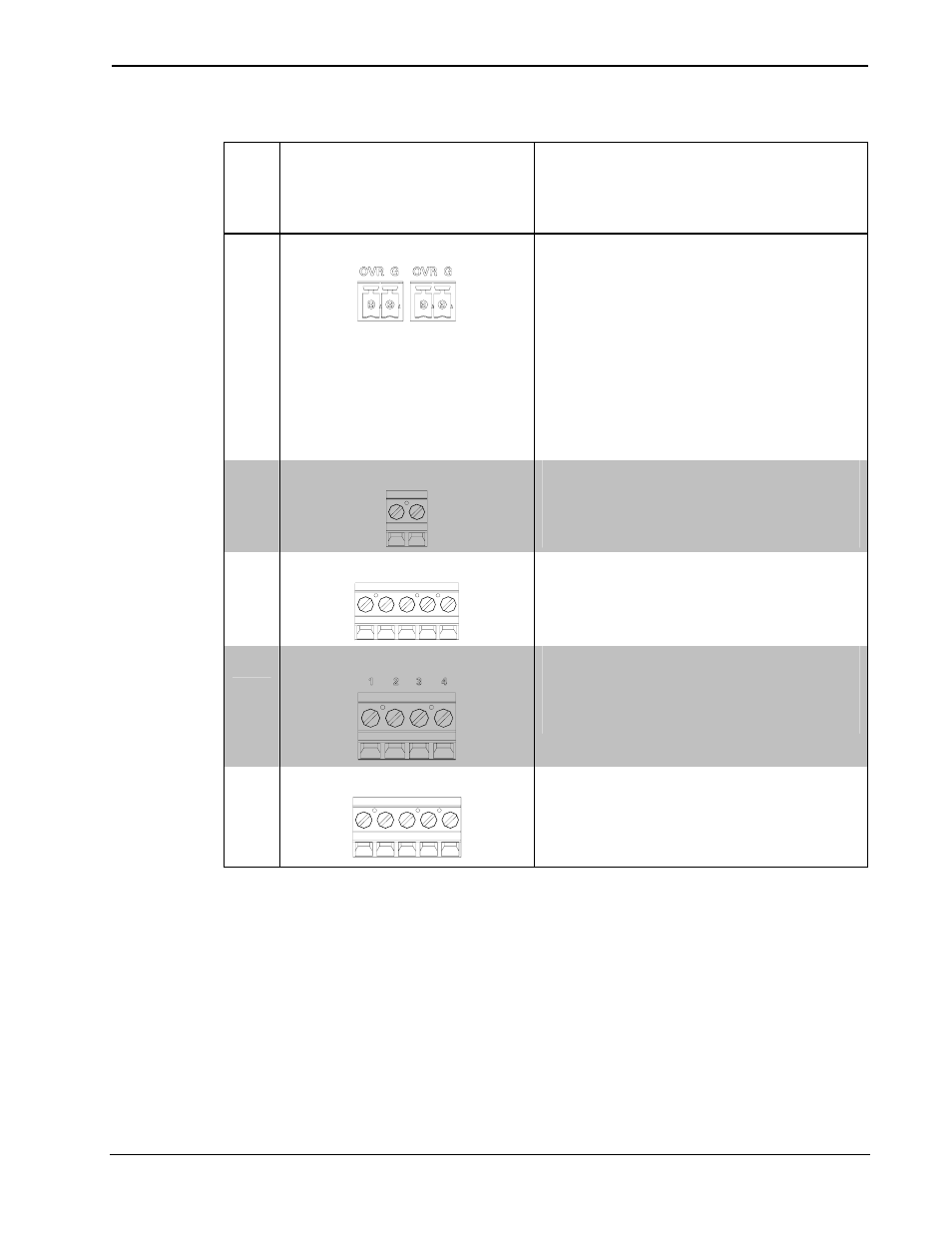
14 OVERRIDE
(2) 2-pin 3.5mm detachable
terminal blocks, paralleled
Sensing input for external low-
voltage contact closure
Activates Override mode when
a closure is present
Minimum Closure Rating:
10mA (per module) at 24 Volts
15
LIVE
(2) Captive screw terminals
2
brown
Line power input
16 NEUTRAL
(5) Captive screw terminals
2
blue
17
DIMMED LIVE (1 – 4)
(4) Captive screw terminals
2
,
red
Dimmer channel outputs 1 – 4
18 GROUND
(5) Captive screw terminals
2
green
1. Interface connectors for NET and OVERRIDE ports are provided with the unit.
2. Captive screw terminals accept up to 2.5 mm
2
(12 AWG) wires per terminal.
10
• DIN Rail Universal Dimmer: DIN-1DIMU4 Operations & Installation Guide – DOC. 6668D