Crestron electronic DIN Rail Universal Dimmer DIN-1DIMU4 User Manual
Page 12
DIN Rail Universal Dimmer
Crestron DIN-1DIMU4
Connectors, Controls & Indicators (Continued)
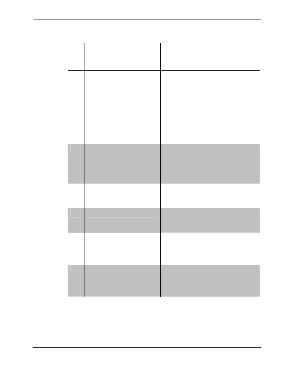
# CONNECTORS
1
,
CONTROLS &
INDICATORS
DESCRIPTION
3 OVR
(LED and Button)
(1) Red LED and (1) miniature
push button for enabling
Override mode and saving
override presets
Maximum wire size: 1.5mm
2
(16 AWG)
For more information, refer to
“Operation” which starts on
page 23.
4
PWR LED
(1) Green LED, normally
indicates AC line power is
connected to either LIVE
terminal, blinks when only
powered by Cresnet
5
NET LED
(1) Yellow LED, indicates
communication with the control
processor
6
RESET
(1) Recessed miniature push
button, resets internal
processor
7
FWD (1 – 4) LED
(4) Red LEDs, illuminate when
a corresponding channel is
operating in a forward phase
mode
8
REV (1 – 4) LED
(4) Red LEDs, illuminate when
a corresponding channel is
operating in a reverse phase
mode
(Continued on following page)
8
• DIN Rail Universal Dimmer: DIN-1DIMU4 Operations & Installation Guide – DOC. 6668D